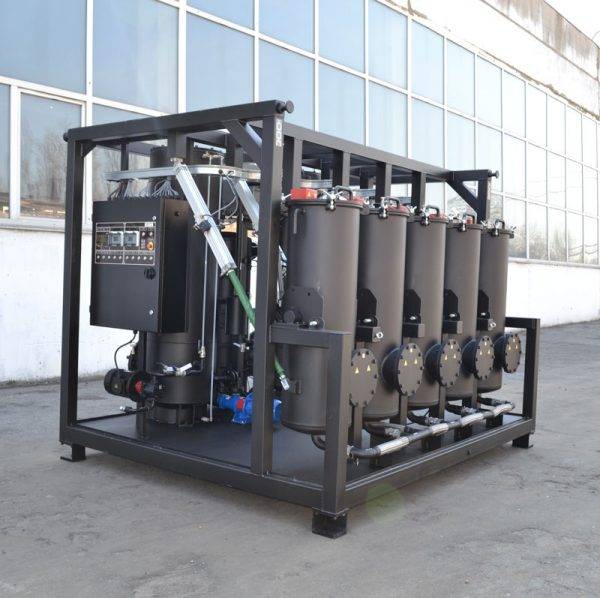
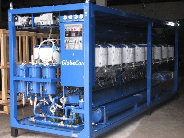
Sorbent Reactivation System CMM-RP4
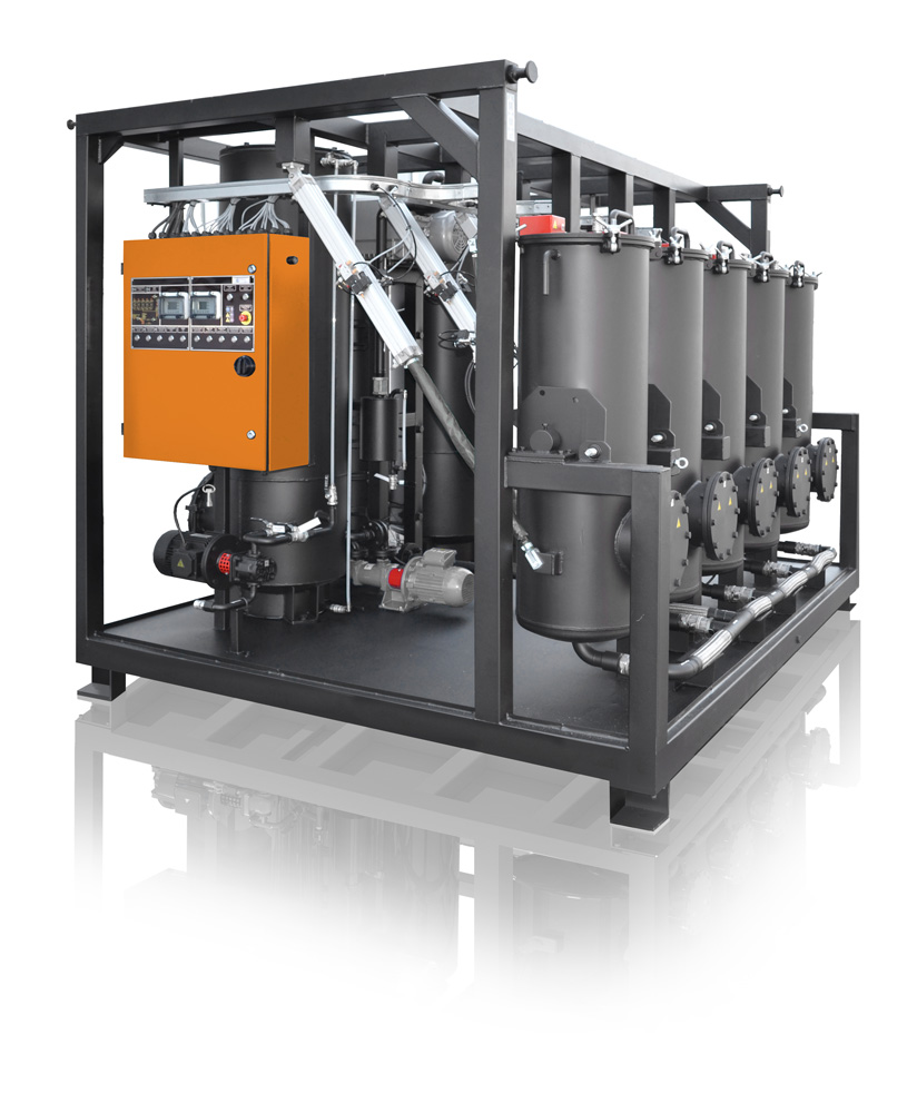
The GlobeCore CMM-RP4 is a stand alone unit designed for the restoration of sorbent material used in the UVR 450/16 system. It can however, be used as an additional section for and with the UVR 450/16 units.
Advantages of CMM-RP4:
- reduce operating costs by 50 to 70% because the same sorbent can be reactivated at least 20 times;
- cut the cost of waste sorbent disposal and eliminate hazardous waste completely;
- reduction of transportation costs; and
- Sorbent that cannot be reactivated can be deactivated for final disposal. After deactivation, the sorbent will not contain oily residues. That is why it can be disposed of as ordinary non-hazardous construction waste (sand) without any damage or danger to the environment.
Before the development of the CMM-RP4, the UVR 450/16 used 360 kg of sorbent. When the sorbent became exhausted, it was normally disposed of as hazardous waste. Now the sorbent used in the UVR 450/16 can be reactivated and placed back in service with the help of the new CMM-RP4 sorbent reactivation unit.
The used sorbent can be reactivated and restored to full service in 24 hours. After being reactivated, the this type of sorbent can be re-loaded into your UVR unit and used again. This will allow you to continue processing oil, fuel, or other fluids without having to replace the sorbent.
Sorbent Reactivation Process:
- The sorbent is loaded into self-tipping columns;
- Open the air inlet valve of the self-tipping columns;
- Start vacuum pump and choose the working pressure with the help of regulating valve; and
- Start heating elements Н1… Н
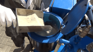
The first loading of the sorbent into UVR-lab
The Heaters will shut off automatically in 40 minutes. At that point, a controlled burn of the sorbent in a low vacuum is started. The cyclical burning and cooling of the sorbent is continued for 24 hours. When the reactivation process is finished, the sorbent will have a residual temperature from between 50 to 80°C. The temperature in the sorbent reactivation columns should be periodically monitored during the reactivation process. The control column has 5 temperature detectors. Each of the other columns are equipped with one upper and with one lower heat sensor. Each sensor shows the temperature level of the burning sorbent. The normal working temperature of the sorbent during the burning process will not exceed 800°C.
The Unit Consists of the Following Components:
- Frame – welded assembly. All the unit components are installed on the frame.
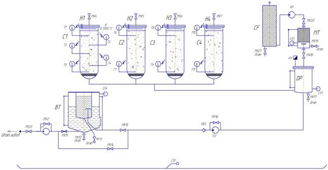
- Buffer Tank BT. The Buffer Tank is used to collect condensate and oil during the reactivation process.
-
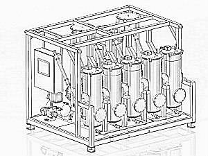
Sorbent reactivation system, 3D-model
Control Panel. The control panel is equipped by registration elements and elements to display information about temperature. The control buttons for the pumps are also on the control panel.
- Coal Filter CF. It cleans the exhaust during reactivation of the sorbent.
- Outlet Pump P1. Is used for pumping condensate and oil from the buffer tank.
- Transfer Pump P2. Is used for pumping oil during sorbent reactivation.
- Self-Tipping Columns C1…C4. Columns where the sorbent reactivation takes place.
- Vacuum Pump VP. Is used for creating vacuum in the system during heating, cooling, and reactivation of the sorbent.
- Intermediate Tank DP. Collects the condensate that was formed during the reactivation process.
- Condensate Tank MT. Condenses moisture and heavy fractions during reactivation of the sorbent.
Circuit diagram
Technical data
| Name of parameter | Value | |
| 1 | Capacity, kg/24 hour |
360 |
| 2 | Sorbent reactivation time, max |
24 |
| 3 | Power consumption, kW |
15 |
| 4 | Power supply voltage |
As required, can be customized |
| 5 | Control system type |
Semi-automatic |
| 6 | Dimensions, mm, max
– length – width – height |
2500 2100 2300 |
| 7 | Weight, kg, max |
2200 |

