Ultrasonic vortex generators AVS-100. Unit application
Cavitation technology application
Cavitational effect is accompanied by microexplosions, ultrasound and also by mechanical cuts and encounters from exposure of the hundred of cuts pairs which are moved towards each other with the high linear speed. The value of that speed is reach to a few dozen of meters per seconds which gives a possibility to cut dispersed matters to the smallest microparticles. In fact it is a micropulse. Per one minute occur hundreds of thousands of micropulses.
The methods of petroleum and petroleum residues processing are based on phase transition which is typical for dispersed system. An effect on phase transitions kinetics can be achieved by chemical agents and physical fields. As a result the nuclear radius is changed, changed also the thickness of adsorptive solvation sphere of compound recurring unit. This unit is an element of petroleum dispersed system. These processes allow increasing the desired petrochemical products yield, improve their quality and reduce energy consumption.
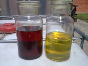
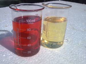
Light fuel product yield increasing
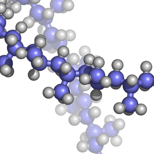
The idea of long-chain organic compounds crushing into short-chain which create a new compounds leads to creation of light fuel products is not new. Those researches were started in the 1960s by soviet scientists. But today, at the time of high prices on the petroleum and its processing cost increase, cavitational technologies are particularly topical.
For today the method of cavitational oil processing is most qualitative. Specific density of light fuel products is increased after cavitational treatment of petroleum.
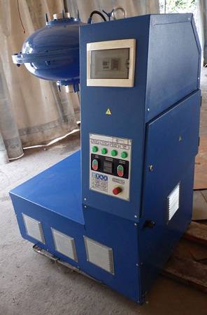
Vortex Cavitational Hardware
The main direction of an ultrasonic vortex cavitational generator application (or AVS unit by PC GlobeCore) is petroleum industry.
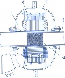
Structure of AVS unit
Cavitational hardwares are used for creation of oil-fuel, oil-mazut mixtures and emulsions. These emulsions are often used to increase the combustion efficiency or utilization of watered fuels.
Cavitational process has a great destruction power which can be used for desintegration of solid substances contained in liquids.
A hard spot crushing is one of the applications of this process which is included to heavy fuels.
This process is also used in order to increase the caloric content of the heavy fuel oil.
Cavitation can be used in fuel treatment process. During this treatment fuel obtains additional purification and at the same time fraction ratio is redistributing to the light fraction. The tests of such fuel are demonstrated decreasing of soluble gum amount.
After treatment by AVS is increasing the quality and caloric content of fuel. As a result we can reach complete fuel burning and decreasing the mass of contaminants. Investigation of cavitation influence on quality of fuel is still urgent and that research is conducted by different private companies and research institutes.
Cavitational devices can increase hydrocarbon fuel viscosity. As a result necessary heating value is decreasing and at the same time is increased fuel spraying dispersion.
AVS unit was created as a reactor for large industrial productivity. This ultrasonic generator can be successfully used for:
- petroleum treatment for pipeline transportation which leads to petroleum viscosity decreasing, destruction of paraffin leads to reduction of the sedimentation on pipe walls;
- pre-cracking petroleum treatment for the purpose of light fraction yield increase.
Experimental Results: Light fuel product yield increasing
Experimental researches show the following results:
– cavitational treatment allows increasing the fraction yield at the same volatilization temperature.
It follows that ultrasonic vibrations accelerate petroleum diffusion in paraffin, intensify the process of paraffin destruction. Acceleration of paraffin dissolution is caused by intensification of oil blending process (on the line oil-paraffin) and influence of pressure surge.
Ultrasonic vortex generators AVS-100. Unit application
Cavitation technology application
Cavitational effect is accompanied by microexplosions, ultrasound and also by mechanical cuts and encounters from exposure of the hundred of cuts pairs which are moved towards each other with the high linear speed. The value of that speed is reach to a few dozen of meters per seconds which gives a possibility to cut dispersed matters to the smallest microparticles. In fact it is a micropulse. Per one minute occur hundreds of thousands of micropulses.
The methods of petroleum and petroleum residues processing are based on phase transition which is typical for dispersed system. An effect on phase transitions kinetics can be achieved by chemical agents and physical fields. As a result the nuclear radius is changed, changed also the thickness of adsorptive solvation sphere of compound recurring unit. This unit is an element of petroleum dispersed system. These processes allow increasing the desired petrochemical products yield, improve their quality and reduce energy consumption.
Light fuel product yield increasing
The idea of long-chain organic compounds crushing into short-chain which create a new compounds leads to creation of light fuel products is not new. Those researches were started in the 1960s by soviet scientists. But today, at the time of high prices on the petroleum and its processing cost increase, cavitational technologies are particularly topical.
For today the method of cavitational oil processing is most qualitative. Specific density of light fuel products is increased after cavitational treatment of petroleum.
Vortex Cavitational Hardware
The main direction of an ultrasonic vortex cavitational generator application (or AVS unit by PC GlobeCore) is petroleum industry.
Cavitational hardwares are used for creation of oil-fuel, oil-mazut mixtures and emulsions. These emulsions are often used to increase the combustion efficiency or utilization of watered fuels.
Cavitational process has a great destruction power which can be used for desintegration of solid substances contained in liquids.
A hard spot crushing is one of the applications of this process which is included to heavy fuels.
This process is also used in order to increase the caloric content of the heavy fuel oil.
Cavitation can be used in fuel treatment process. During this treatment fuel obtains additional purification and at the same time fraction ratio is redistributing to the light fraction. The tests of such fuel are demonstrated decreasing of soluble gum amount.
After treatment by AVS is increasing the quality and caloric content of fuel. As a result we can reach complete fuel burning and decreasing the mass of contaminants. Investigation of cavitation influence on quality of fuel is still urgent and that research is conducted by different private companies and research institutes.
Cavitational devices can increase hydrocarbon fuel viscosity. As a result necessary heating value is decreasing and at the same time is increased fuel spraying dispersion.
AVS unit was created as a reactor for large industrial productivity. This ultrasonic generator can be successfully used for:
- petroleum treatment for pipeline transportation which leads to petroleum viscosity decreasing, destruction of paraffin leads to reduction of the sedimentation on pipe walls;
- pre-cracking petroleum treatment for the purpose of light fraction yield increase.
Experimental Results: Light fuel product yield increasing
Experimental researches show the following results:
– cavitational treatment allows increasing the fraction yield at the same volatilization temperature.
It follows that ultrasonic vibrations accelerate petroleum diffusion in paraffin, intensify the process of paraffin destruction. Acceleration of paraffin dissolution is caused by intensification of oil blending process (on the line oil-paraffin) and influence of pressure surge.
 The efficacy of cavitational reactors can be significantly enhanced by combining cavitation with other oxidation processes or by using catalysts and/or additives.
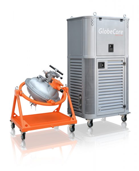 While wastewater treating from phenol, oxidized another organic impurities. Level of formaldehyde content decreases from 10 g/dm3 to 50-100 mg/dm3, methanol – from 6.4 g/dm3 to 2.3 mg/dm3, diphenylol propane – from 4.6 g/dm3 to 150 mg/dm3.
 The mode of obtaining of modified liquid hydrocarbon fuel includes mixing of hydrocarbon components and the water by means of rotate electromagnetic field. Ratio of the hydrocarbon component and water is 60 to 40 and 98 to 2.
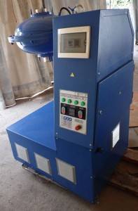
 The one of the main problems of contemporary construction material production is problem of obtaining concrete compositions of high quality. The possible way to resolving this problem is modification of a cement stone structure that allows using all durability potential of the crystalline hydrates and also increases the quality of all concrete components. We have investigated the ways of concrete quality improvement by using nanotechnologies and nanomaterials such as magnetic activation.
 In the process of expanded clay production the argillous raw material homogenizes and mills in the drilling mud mixers and rollers. But these equipments not ensure qualitative desintegration. As result we obtain the expanded clay of low quality.
 Cellular concrete is made in result of solidification preliminarily blown-out mixture of the cementing medium, water, silicious component using gasifier of components. Most frequently as foaming agent used aluminum powder. The aluminum powder reacts with water solution of calcium hydroxide and disengages hydrogen.
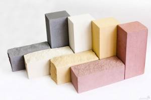 The raw material for the silica brick production is the high-silica sand (92-95% of dry mixture) and the lime (5-8%). Structural capabilities of the brick directly depend from the degree of activation of SiO2 andmixing uniformity of components.