The “Vortex Layer” Machine AVS-100 can be used in the chemical and power industries. Additionally, this machine is designed to purify industrial and household waste water.
The “Vortex Layer” machine consists of a working chamber (pipeline) with a diameter that ranges from 60 to 330 mm (millimeter). This working chamber is arranged in the inductor that creates a rotating magnetic field. Inside the pipeline there are cylindrical ferromagnetic particles. The amount of these particles depends on the volume of the pipeline’s active zones.
The main parts of the “Vortex layer” machine are as follows: (1) an inductor that creates a rotating magnetic field; (2) the cooling system, and (3) the working chamber with the ferromagnetic particles. Under the influence of a rotating magnetic field, the ferromagnetic particles move around in the active zone and create a so-called “vortex layer.” Such a design allows for proper processing of liquids as well as trouble-free machine servicing.
The following is the discussion of the counterparts that had been previously patented.
There exists a counterpart of the vortex layer machine that consists of: (1) two consecutive active zones of the pipe with active ferromagnetic particles inside; and (2) external electromagnetic inductors, which create a rotating magnetic field (can rotate in both directions). The input deflectors of the pipe’s active zones direct the liquid opposite to the rotating magnetic field direction. The output deflectors retain particles in the active zones of the pipes. In both active zones, there is a rotating magnetic field, which voltage, frequency, and rotation direction may be adjusted.
But still, this machine has disadvantages such as:
(1) the design of the equipment is poorly adapted for use;
(2) high levels of material and energy consumption while processing liquid; and
(3) the wear of the machine’s active zone surfaces may result in the breakdown of the equipment.
Due to high quality of the liquid processing and trouble-free servicing, the Vortex Layer machine AVS -100 is considered to be much better than its counterpart.
Fig. 1 shows an electromagnetic unit with vortex layer.
Figure 1.
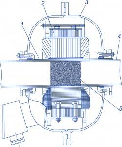
The schematic diagram of the electromagnetic unit with the vortex layer: 1 – Protective bushing, 2 – inductor that creates rotary electromagnetic field, 3 – inductor frame, 4 – the working chamber (non-magnetic material), 5 – ferromagnetic particles
The AVS-100 unit typically consists of two parts: the unit itself and the control unit.
The unit is secured to the support with pivot bolts that makes it possible to set the desired tilt angle of the active chamber with a subsequent installation on the processing line. Control and protection devices are in the upper part of the control unit. At the bottom of the unit there is the inductor’s cooling system.
The “Vortex Layer” machine may be applied in various industries because of its unique design.