Transformer Oil Regeneration Plant CMM-R2
Unit design
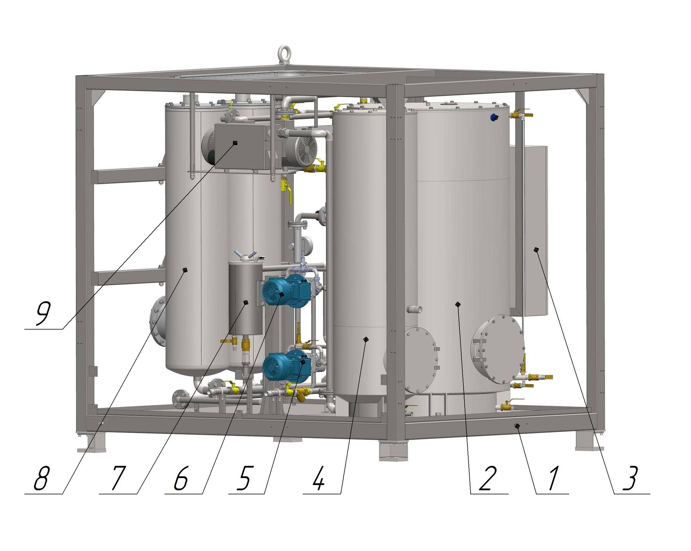
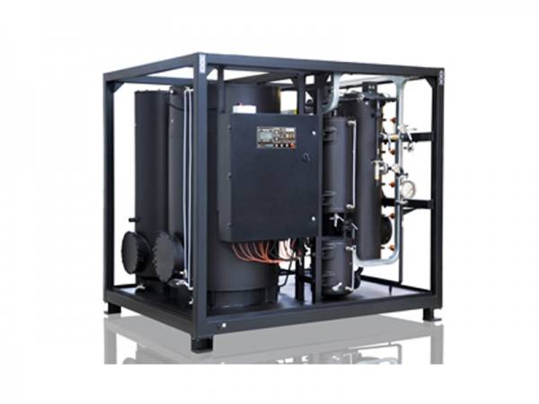
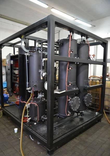
Figure 1. General view of the unit
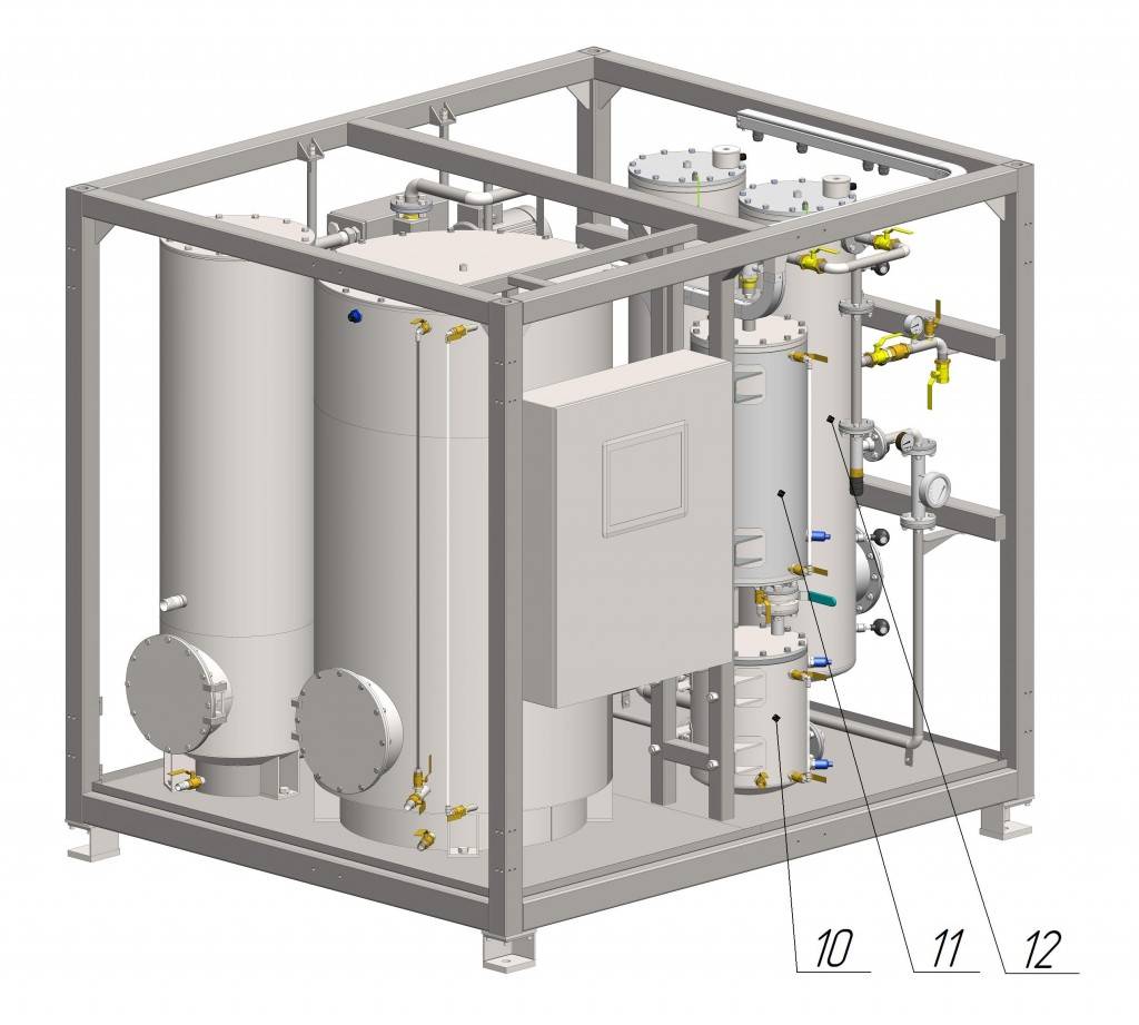
Figure 2. General view of the unit
The unit consists of the following components:
- Frame – welded. The frame supports all components.
- Buffer tank. This oil tank contains the oil for priming the unit and condensate for discharge.
- Electric control cabinet. The cabinet contains components for registration and display of temperature indications, as well as pump control buttons.
- Charcoal filter. This component purifies exhaust during sorbent reactivation.
- Input pump. Pumps the oil into the unit.
- Transfer pump. Pumps the oil during sorbent reactivation.
- Filter. Filter the oil.
- Right-hand column. Regenerates transformer oil.
- Vacuum pump. Creates vacuum in the system during sorbent reactivation.
- Intermediary tank. Separates air bubbles during regeneration of oil, also collects and removes condensate formed during reactivation.
- Oil collector. Condenses moisture and heavy fractions during sorbent reactivation.
- Control column. Regenerates transformer oil.
Unit installation.
The unit must be placed on a foundation. The unit does not require anchorage to the foundation. When installing the unit, consider ease of maintenance, pipeline and electric cable connections, as well as operation safety.
The placement area must be equipped with a water drainage facility.
Unit operation
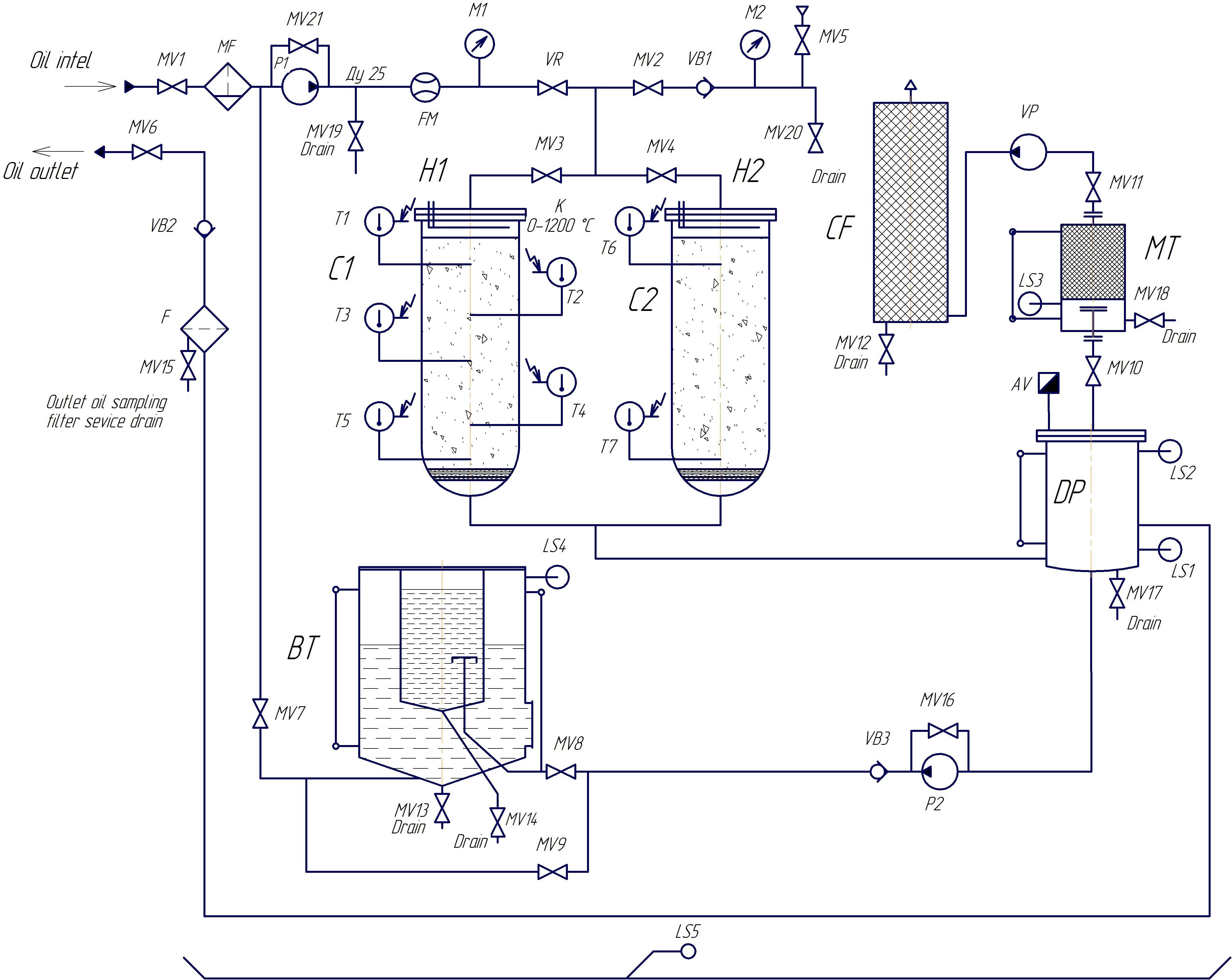
Figure 3. Flow diagram.
Flow diagram description
| Position | Item | Description |
| MV1 | Ball valve | Oil input valve |
| MF | Mesh filter | Captures large solid particles |
| Р1 | Input pump | Draws in the oil for processing |
| MV21 | Ball valve | Bypass valve |
| MV19 | Ball valve | Sampling valve |
| FM | Flowmeter | Indicates instantaneous flow rate |
| М1 | Axial manometer 0-10 bar ф63 | |
| VR | Regulation valve | Cuts off the vacuum line during oil regeneration. |
| MV2 | Ball valve | Air cut off valve |
| VB1 | Return valve | |
| М2 | Radial vacuum meter -1 to 0 bar | |
| MV5 | Ball valve | Air input valve |
| MV20 | Ball valve | Column cooling |
| MV3, МV4 | Ball valve | Oil to columns |
| Н1, Н2 | Heater | Sorbent reactivation |
| Т1-Т7 | Thermistor 0-1200С | Temperature control during reactivation of sorbent |
| С1-С2 | Sorbent column | Transformer oil regeneration |
| DP | Drain pot | In this vessel, air bubbles are separated during oil regeneration; also, condensate formed during sorbent reactivation is collected and pumped out |
| AV | Air release valve | Removal of air from DP |
| LS1 | Level sensor | Indicates oil in the bottom of the DP |
| LS2 | Level sensor | Indicates oil in the top of the DP |
| MV10 | Ball valve | Oil collector cut off |
| MV17 | Ball valve | Oil drain from DP |
| MT | Oil collector | Condensation of moisture and heavy fractions during reactivation |
| LS3 | Level sensor | Max level of liquid in the oil collector |
| MV18 | Ball valve | Condensate drain from the oil collector |
| MV11 | Ball valve | Vacuum cut off valve |
| VP | Vacuum pump | Creates vacuum in the system during reactivation |
| CF | Charcoal filter | Purifies exhaust during reactivation |
| MV12 | Ball valve | Drains condensate from charcoal filter |
| Р2 | Transfer pump | Pumping of processed fluid |
| MV16 | Ball valve | Bypass valve |
| VB3 | Return valve | Prevents oil from being sucked into DP |
| ВТ | Buffer tank | The oil tank is used to prime the unit with oil and to collect condensate |
| LS4 | Level sensor | Limits oil level in the buffer tank |
| MV8 | Ball valve | Settling vessel cut off valve |
| MV9 | Ball valve | Buffer tank cut off valve |
| MV13 | Ball valve | Condensate and bad oil drain from buffer tank |
| MV14 | Ball valve | Settling tank drain valve |
| MV7 | Ball valve | Oil supply from buffer tank |
| F | Filter | Oil filtration |
| MV15 | Ball valve | Sampling and drain valve |
| VB2 | Return valve | |
| MV6 | Ball valve | Oil outlet valve |
| LS5 | Oil level sensor | Stop the unit if an oil leak is detected |
The electrical components of the unit are controller from the control cabinet, which contains connections, controls and measuring systems.
CMM-R2 during factory quality acceptance testing
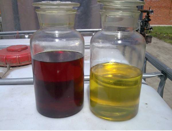
Transformer Oil regenerated by CMM-R