Category Archives: News

Cyano-containing wastewater treatment machine

 Application of cyanides

Cyanides are employed in a number of chemical processes, including fumigation, case hardening of iron and steel, electroplating, and the concentration of ores.

Electrolytic metallurgy is one of the productions which have the serious influence on contamination of the environment, particularly by heavy metal ions. The main supplier of toxicants in electroplating is cleaning-purposes water. At the same time this water is the main source of wastewater.

By the reason of imperfect washing method is released the large volume of wastewater. (The known washing method requires up to 2 m3 of cleaning-purposes water for washing 1 m3 of details).

The wastewater from electroplating shops contains toxic pollutants such as cyanogen, chromium, copper, lead, acid, alkali and others.

Compared to other sewages from electroplating shops cyano-containing wastewaters are of high toxicity. The median lethal human dose of hydrocyanic acid is 1 mcg/kg (for sodium cyanide this dose is 1,8 mcg/kg, for potassium cyanide is 2,4 mcg/kg). That why all cyano-containing wastewater sterilization jobs shall be carried out with compliance of all safety requirements


Cyano-Containing Wastewater


The most toxic industrial wastewater is that which contain simple cyano-compound (with ions CN—), combined compounds [Cu(CN2)], [Cu(CN3)-2], [Zn(CN4)-2]. General concentration of simple and combined cyanides is ranging from 10-15 to 150-300 mg/l.

To neutralize the high-toxic cyanides (simple cyanides, ammonocarbonous acid, compound zinc cyanide, copper, nickel, cadmium) need to apply oxidizing by reagents which contain available chlorine.

Reagent method is wide used for cyanides neutralization. For example, cyanides can be neutralized by oxidization using calcium hypochlorite Ca(OCl)2 or chloride lime CaOCl2,or gaseous chlorine.

On the enterprises the most of cyano-containing wastewater is neutralized by means of intermittently operating plants. In these plants reagentizing is made in tanks which are filling one-by-one.

Large amounts of wastewater are treated by using continuously operating plants.

The reaction proceeds in 2 stages. Stage 1 changes cyanides to cyanates (pH level is equal to 10÷11,5). In stage 2 cyanates hydrolyzed to nitrogen and carbon dioxide (pH level is equal to 7÷7,5).

State-of-the-art technology: vortex layer


Utilization of AVS unit (Intensifier of Technological Process or Magnetic Vortex Activator) gives a possibility to combine oxidization of cyanides and its decomposition to carbonate and ammonia in one stage on following conditions: reaction proceeds in alkaline medium, pH level 9÷10.

To find out more about vortex layer of ferromagnetic particles which rotated in electromagnetic fields you need only clicked this link

In the industrial implementation of the proposed method cyano-containing wastewater is fed to an equalizing reservoir from the source of their creation. Passing the reservoir these wastewater are pumping into the AVS unit. At the same time alkaline agent and oxidizer are fed to the working chamber of the unit.

The signalling indicator of cyanogen and pH-meter are controlling pH level in the AVS unit and cyanides residue level. From the AVS unit the wastewater fed to collector where they mix with neutralized wastewater obtained from other electroplating shops.

As alkaline reagent can be used lime and soda in the form of 5-10% solution. As oxidizer can be used calcium hypochlorite or sodium hypochlorite, chlorine or chloride lime. The oxidizer consumption is on level 110% from stoichiometric prediction.

In the table 1 you can see the result of investigations obtained during the testing of AVS unit on cyano-contained wastewater treatment. The productivity of this unit is 12-15 m3/h.

 Table 1

The results of cyano-containing wastewater treatment by using AVS-100

Cyan-ions: initial content, mg/l

Cyan-ion content after treatment, mg/l

8000

0,12

2300

0,09
4320

0,02

50

0,02
62,4

0,0011

34,3

0,0014

It was observed that the quality of treatment is not depending from the concentration of cyan-ion in the initial wastewater.


Case study: successful implementation of AVS unit


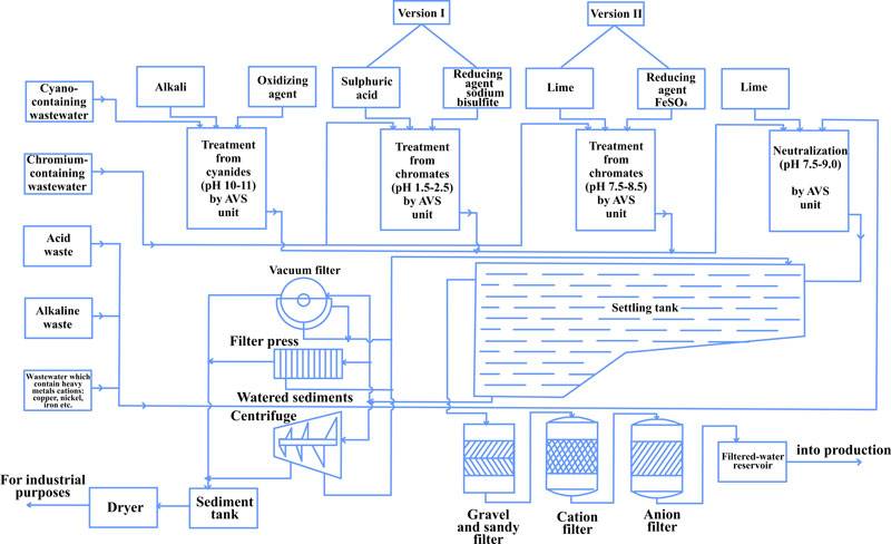
 Engineers from PC GlobeCore have investigated and implemented in real electroplating shop the process flowsheet of uninterrupted and simultaneously wastewater treatment from cyanides, cyanates and hexavalent chromium compounds.

 According to this process flowsheet (figure 1) the wastewater is treated in three separate flow lines:

I – restoration hexavalent chromium Cr+6 to trivalent chromium Cr+3 in chromium-containing wastewater;

II – oxidization of cyanides to cyanates in cyano-containing wastewater;

III – simultaneous wastewater treatment after mixing neutralized chromium-containing wastewater and cyano-containing wastewater with acid-base wastewater.

To wastewater demineralization is used the gravel and sandy filter, cation and anion filters. Passing all these filters the water is fed to the filtered-water reservoir and into production.

See the figure 1.


Schematical diagram of cyano-containing wastewater treatmnent

Schematical diagram of cyano-containing wastewater treatmnent

Advantages of AVS unit application


Offered by us wastewater treatment methods are very effective and some of them allow reduce reagent consumption in 1.5-2 times, reduce energy consumption in 2 times and decrease working area of treatment facilities in 10-15%.

PC GlobeCore is combined of scientific research, engineering design, technical service, product development and manufacturing. You can be sure – all our products are based on breakthrough technologies and are environmentally friendly, tested by qualified engineers, fit for use and are so simple to operate that you will need only one operator.

Coal-Water Fuel production: application of AVS-100

What is “coal-water fuel”?

 Coal-water fuel (CWSF or CWS or CWF) is a fuel which consists of fine dispersed coal particles, water and plasticizing agent. This type of fuel is widely used as an alternative to gas and black oil on different heat generating facilities. Operational economy is the main of advantages of the coal-water fuel. CW fuel has almost the same heat transfer level that the most expensive gas and black oil. Coal is cheaper in many times by comparison with gas and black oil.

Coal water fuel CWF globecore

 Characteristics of coal-water fuel are follows:

  •  rheological (viscosity, bias potential);
  • sedimentation (static and dynamic conditions homogeneity saving);
  • combustible (energy potential, combustion efficiency).


If you don’t found on this website the information you need concerning application of AVS unit, you can contact directly with the manager in charge of AVS unit by using only following email: [email protected] or skype: bichurina_globecore and we will prepare for you all required information as soon as possible

Properties of coal-water fuel:

  • flammability point – 800-850°С;
  • burning temperature – 950-1150°С;
  • calorific capacity – 3700-4700 kcal;
  • carbon burning degree is up to 99%.

 Coal-water fuel production technology

 CWF consists from 55-70% of fine dispersed coal particles, 30-45% of water and plasticizing agent. Water content provides the reduction of hazardous emission to the atmosphere and transforms coal to explosion- and fireproof material.

The cost of coal is in 3 times lower than the cost of heating oil. In spite of all market’s fluctuations of coal prices, the balance between prices on fuel from heating oil and coal-water fuel is on the same level.

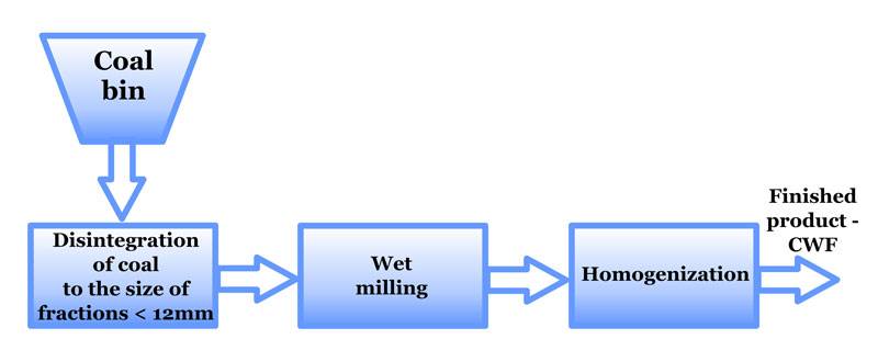
 Coal-water fuel production process consists of three main phases:

 First phase – preliminary disintegration to the fraction size 3-12 mm. If the slurry coal of fine fraction is used as raw material you can exclude this phase.

 Second phase – wet milling in the ball mills to the fraction size

 Third phase – homogenization. On this phase is eliminated all irregularities of coal particles distribution inside of suspension, are supplemented plasticizing agents and stabilizers. On third phase CWF acquires the necessary homogeneous properties.

Phases of the coal-water fuel production process

Phases of the coal-water fuel production process

 Coal disintegration is the main goal that should be resolved during the CWF production process. Rheological properties and burning process stability are in the directly-proportional dependence from the stability of coal desintegration process with preset parameters and clear abidance of additive concentrations.

 Hammer grinders and ball mills of different types can be used for desintegration of coal, combustible schist or carbon residues.

 Among various existing methods of coal grinding, uninterrupted wet milling ball mills are the most widespread today.

 Pre-grinded to the fraction 3-6 mm coal particles are transferred to ball mills for further grinding. At the same time, water and additive are going to the ball mill. The coal is grinding in the mill to the size of fractions 0-3 mcm. After addition of all components, material is going back to the mill for further intensive grinding.

 Implementation of the Intensifier of Technological Process AVS-100 to CWF production process

 As we already noticed in our preceding articles, Intensifiers of Technological Process have a number of advantages to compare with other types of grinding equipments. These advantages are:

  • extremely, in tens and hundreds times acceleration of chemical and physical processes;
  • increasing of product yield quality;
  • decreasing of raw materials consumption;
  • decreasing of energy consumption;
  • decreasing of working space and others.

 Refer to following results of powder desintegration by AVS and different mills.

 Table 1

Type of equipment

Power consumption, kW

Productivity,

kg/h

Fraction yield – 3 mcm, %

AVS

1,5

> 2

50

Ball mill (wet milling)

0,5

> 1

7-15

Ball mill (dry milling)

0,5

> 2

1-3

Centrifugal mill

0,6

to 10

5

Hammer mill

2,0

> 80

5

As you can see from the table, application of AVS unit leads to considerable economy of duration of the process of material production (in 3 times), and at the same time we obtain in 5-6 times more product than if we would use ball mill with wet milling.

 It should also be noted that application of the AVS unit is the most effective for material regrinding process. Besides, vortex layer machines allow obtaining the product with the higher degree of particle fineness. Development by engineers from PC GlobeCore equipments allow intensify most of technological processes and raise production standards and exclude ball mills and vibration mills which are the sources of raised noise and dusting.

Mayonnaises and sauces production: AVS-100 application

Our scientists have designed technologies which use electromagnetic units with ferromagnetic particles for production of low-, middle- and high-calorie sauces based on the emulsion with fat content mass from 20 to 74%.

AVS-100 mayonnaise production

 Suggested technology allows obtaining the mayonnaise with the high degree of microbiological safety and high organoleptic indicators. Obtained mayonnaises are stable and not separate over the long period of time (3-12 month) depending from the concentration.

 During processing time takes place the continuous material dispersion and homogenization. Homogenization of poor-dispersion emulsion in the working chamber leads to increasing of emulsifying capacity of emulsifiers caused by optimum molecules polarization.

 Besides, application of AVS unit allows intensifying technological process thanks to exception some technological operations. As the result we can decrease the price of finished products.

Follow the link to find out more about application of AVS unit in the food industry

Coming soon: the real case study about mayonnaises production technology 

Case study: How to purify Hexavalent Chrome Wastewater

We all talk about priority pollutants, about hazardous substances and discharge to the atmosphere etc. which are dangerous for our environmental. Day by day we adopt new laws and regulations to protect our green future. So, what is that “priority pollutants”? Priority pollutants are highly toxic chemicals. The list of these chemicals is quite large and includes thousands of items but today we will speak about hexavalent chromium and methods of chromium-containing wastewater treatment.

Wastewater which contains chromium and other heavy metals is classified as high toxic wastewater. For this type of wastewater is required qualitative and effective treatment.

 Hexavalent Chrome is priority pollutant and exists in several forms. Industrial use of chromium includes in metal alloys such as stainless steel; protective coatings on metal; magnetic tapes; and pigments for paints, cement, paper, rubber, composition floor covering and other materials. Hexavalent chromium can be formed when performing “hot work” such as welding on stainless steel or melting chromium metal.
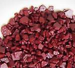
Hexavalent Chromium Compound

Hexavalent Chromium Compound

Exposure to this chemical is prevalent in different industrial applications. For this reason there exist a lot of international Standards, Directives and Acts which regulate utilization of chromium compounds and obligate to recycle chromium-containing waste. Besides, removal of chrome from wastewater is also needed to achieve the water quality level needed for reuse and recycling.

There are different chromium removal methods such as chemical precipitation, adsorption and biosorption, reverse osmosis, ion exchange, electrodialysis, photo-catalysis. We offer to use breakthrough technology – electromagnetic vortex layer with rotating ferromagnetic particles (AVS-100 or Intensifier of Technological Process).

As we already noted in our previous articles, offered method is very effective and allows reduce reagent consumption in 1.5-2 times, reduce energy consumption is 2 times and decrease working area of treatment facilities in 10-15%.

Let us remember the result of sterilization of chromium-containing wastewater.

The results of sterilization of chromium-containing wastewater by using AVS

Basic concentration value Cr6+, mg/dm3

pH process

Consumption of iron sulfate, % from stoichiometric consumption

Ferromagnetic element mass, g

Residual Cr6+ content after purification, mg/dm3

100

2

100

150

0

90

0

80

0,56

100

4

90

150

0

80

0,9

590

2

100

200

0

90

0

80

0,8

1000

2,5

100

200

0

90

0,11

80

1,1

200

7,5

100

150

0,012

200

9,0

100

150

0

90

0,05

80

0,98

750

7,5-8,5

90

200

0,1-0,01


As you can see from the table, the content of chromium compounds in water tends to zero after treatment by using AVS unit.

The goal of this article is to show how it works. How can we reach the complete purification of wastewater from chromium? So, let`s begin.

Typically wastewater which contains chromium compounds treated in 2 stages. First we need change hexavalent chromium Cr6+ to trivalent chromium Cr3+. As result we need obtain non-toxic materials.

Engineers from PC GlobeCore have investigated the effectiveness of AVS usage in following versions: I – sterilization of chromium-containing wastewater by reduction hexavalent chromium to trivalent chromium, II – combined neutralization of chromium-containing and acid-base wastewater with simultaneous purification from heavy metals ions.

The results of neutralization and purification from heavy metal ions are follows:

Basic metal concentration, mg/dm3

pH process

Consumption of Ca(OH)2, % from stoichiometric consumption

Ferromagnetic element mass, g

Residual metal content, mg/dm3

Fe2+;3+= 130,0

7,5

90,0

200,

Fe2+;3+ –  0

Cu2+= 50,0

Cu2+ –  0,12

Zn2+= 45,0

Zn2+ –  0,063

Cd2+= 10,0

Cd2+ –  0,07

Cr3+= 120,0

Cr3+ –  0

Fe2+;3+= 170,0

8,5

100,0

150

Fe2+;3+ –  0

Cu2+= 40,0

Cu2+ –  0,018

Zn2+= 28,0

Zn2+ –  0

Cd2+= 5,5

Cd2+ –  0,011

Cr3+= 100,0

Cr3+ –  0

Fe2+;3+= 250,0

8,7

100,0

200

Fe2+;3+ –  0

Cu2+= 65,0

Cu2+ –  trace

Zn2+= 35,0

Zn2+ –  trace

Cd2+= 2505

Cd2+ –  0

Cr3+= 350,0

Cr3+ –  0


On the basis of performed investigations and production experiments of AVS application for wastewater treatment, we offered and implemented manufacturing schemes of wastewater treatment on different treatment facilities.

On the figure 1 is shown the diagram of simultaneous treatment of chromium-containing and acid-base wastewater.
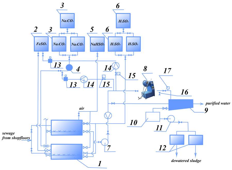
Figure 1. The diagram of simultaneous treatment of chromium-containing and acid-base wastewater: 1 - mixing cylinder; 2 – tank for reducing agent (solution FeSO4); 3 – tank for Na2CO3 solution preparation; 4, 7, 11 – pumps; 5 - tank for reducing agent; 6 – tank for sulphuric acid; 8 – AVS unit, 9, 10 – settling tank; 12 - vacuum filter; 13 - dosing unit; 14 - flow rate meter; 15 – reagent consumption control valve; 16 - sampling unit; 17 – pH-meter

Figure 1. The diagram of simultaneous treatment of chromium-containing and acid-base wastewater:
1 – mixing cylinder; 2 – tank for reducing agent (solution FeSO4); 3 – tank for Na2CO3 solution preparation; 4, 7, 11 – pumps; 5 – tank for reducing agent; 6 – tank for sulphuric acid; 8 – AVS unit, 9, 10 – settling tank; 12 – vacuum filter; 13 – dosing unit; 14 – flow rate meter; 15 – reagent consumption control valve; 16 – sampling unit; 17 – pH-meter

According to this diagram, sewage from shopfloors is alternately entering into two mixing cylinders. When the first of these cylinders is filled by sewage and this sewage is neutralized, to cylinder is fed the acid (in order to acidize the sewage to 2-3 pH level) and is fed reducing agent (sodium bisulfite). After 5-10 minutes mixing this sewage is fed into AVS unit. (Before adding the sewage into AVS, this sewage was filled by Na2CO3 to obtain the value of pH level at elevation 7,5-9). During couple seconds of processing in AVS unit can be achieved complete and effective wastewater treatment by reagents. During this time is completed restoration of Cr6+ to Cr3+ and formation of Cr3+ hydroxide and other heavy metals. As reducing agent can be used FeSO4 (ferrous sulfate).

In this case chromium restoration can be provided in each of acid and base medium. The wastewater with metal hydroxides (after processing in AVS unit) enters the settling tank for defecation and then – the sewerage or the water recycling (to the shopfloors for engineering purpose). The sludge from settling tank is dewatered by vacuum filters.

In conclusion it should be noted that application of AVS unit allows obtaining the quality of treatment lower than maximum permissible concentration, reduce reagent consumption in 1,5-2 times, reduce energy consumption in 2 times and decrease working area of treatment facilities in 10-15%.

We all talk about priority pollutants, about hazardous substances and discharge to the atmosphere etc. which are dangerous for our environmental. Day by day we adopt new laws and regulations to protect our green future. So, what is that “priority pollutants”? Priority pollutants are highly toxic chemicals. The list of these chemicals is quite large and includes thousands of items but today we will speak about hexavalent chromium and methods of chromium-containing wastewater treatment.

 Hexavalent Chrome is priority pollutant and exists in several forms. Industrial use of chromium includes in metal alloys such as stainless steel; protective coatings on metal; magnetic tapes; and pigments for paints, cement, paper, rubber, composition floor covering and other materials. Hexavalent chromium can be formed when performing “hot work” such as welding on stainless steel or melting chromium metal.

Hexavalent Chromium Compound

Hexavalent Chromium Compound

Exposure to this chemical is prevalent in different industrial applications. For this reason there exist a lot of international Standards, Directives and Acts which regulate utilization of chromium compounds and obligate to recycle chromium-containing waste. Besides, removal of chrome from wastewater is also needed to achieve the water quality level needed for reuse and recycling.

 Wastewater which contains chromium and other heavy metals is classified as high toxic wastewater. For this type of wastewater is required qualitative and effective treatment.

There are different chromium removal methods such as chemical precipitation, adsorption and biosorption, reverse osmosis, ion exchange, electrodialysis, photo-catalysis. We offer to use breakthrough technology – electromagnetic vortex layer with rotating ferromagnetic particles (AVS-100 or Intensifier of Technological Process).

As we already noted in our previous articles, offered method is very effective and allows reduce reagent consumption in 1.5-2 times, reduce energy consumption is 2 times and decrease working area of treatment facilities in 10-15%.

Let us remember the result of sterilization of chromium-containing wastewater.

The results of sterilization of chromium-containing wastewater by using AVS

Basic concentration value Cr6+, mg/dm3

pH process

Consumption of iron sulfate, % from stoichiometric consumption

Ferromagnetic element mass, g

Residual Cr6+ content after purification, mg/dm3

100

2

100

150

0

90

0

80

0,56

100

4

90

150

0

80

0,9

590

2

100

200

0

90

0

80

0,8

1000

2,5

100

200

0

90

0,11

80

1,1

200

7,5

100

150

0,012

200

9,0

100

150

0

90

0,05

80

0,98

750

7,5-8,5

90

200

0,1-0,01


As you can see from the table, the content of chromium compounds in water tends to zero after treatment by using AVS unit.

The goal of this article is to show how it works. How can we reach the complete purification of wastewater from chromium? So, let`s begin.

Typically wastewater which contains chromium compounds treated in 2 stages. First we need change hexavalent chromium Cr6+ to trivalent chromium Cr3+. As result we need obtain non-toxic materials.

Engineers from PC GlobeCore have investigated the effectiveness of AVS usage in following versions: I – sterilization of chromium-containing wastewater by reduction hexavalent chromium to trivalent chromium, II – combined neutralization of chromium-containing and acid-base wastewater with simultaneous purification from heavy metals ions.

The results of neutralization and purification from heavy metal ions are follows:

Basic metal concentration, mg/dm3

pH process

Consumption of Ca(OH)2, % from stoichiometric consumption

Ferromagnetic element mass, g

Residual metal content, mg/dm3

Fe2+;3+= 130,0

7,5

90,0

200,

Fe2+;3+ –  0

Cu2+= 50,0

Cu2+ –  0,12

Zn2+= 45,0

Zn2+ –  0,063

Cd2+= 10,0

Cd2+ –  0,07

Cr3+= 120,0

Cr3+ –  0

Fe2+;3+= 170,0

8,5

100,0

150

Fe2+;3+ –  0

Cu2+= 40,0

Cu2+ –  0,018

Zn2+= 28,0

Zn2+ –  0

Cd2+= 5,5

Cd2+ –  0,011

Cr3+= 100,0

Cr3+ –  0

Fe2+;3+= 250,0

8,7

100,0

200

Fe2+;3+ –  0

Cu2+= 65,0

Cu2+ –  trace

Zn2+= 35,0

Zn2+ –  trace

Cd2+= 2505

Cd2+ –  0

Cr3+= 350,0

Cr3+ –  0


On the basis of performed investigations and production experiments of AVS application for wastewater treatment, we offered and implemented manufacturing schemes of wastewater treatment on different treatment facilities.

On the figure 1 is shown the diagram of simultaneous treatment of chromium-containing and acid-base wastewater.

Figure 1. The diagram of simultaneous treatment of chromium-containing and acid-base wastewater: 1 - mixing cylinder; 2 – tank for reducing agent (solution FeSO4); 3 – tank for Na2CO3 solution preparation; 4, 7, 11 – pumps; 5 - tank for reducing agent; 6 – tank for sulphuric acid; 8 – AVS unit, 9, 10 – settling tank; 12 - vacuum filter; 13 - dosing unit; 14 - flow rate meter; 15 – reagent consumption control valve; 16 - sampling unit; 17 – pH-meter

Figure 1. The diagram of simultaneous treatment of chromium-containing and acid-base wastewater:
1 – mixing cylinder; 2 – tank for reducing agent (solution FeSO4); 3 – tank for Na2CO3 solution preparation; 4, 7, 11 – pumps; 5 – tank for reducing agent; 6 – tank for sulphuric acid; 8 – AVS unit, 9, 10 – settling tank; 12 – vacuum filter; 13 – dosing unit; 14 – flow rate meter; 15 – reagent consumption control valve; 16 – sampling unit; 17 – pH-meter

According to this diagram, sewage from shopfloors is alternately entering into two mixing cylinders. When the first of these cylinders is filled by sewage and this sewage is neutralized, to cylinder is fed the acid (in order to acidize the sewage to 2-3 pH level) and is fed reducing agent (sodium bisulfite). After 5-10 minutes mixing this sewage is fed into AVS unit. (Before adding the sewage into AVS, this sewage was filled by Na2CO3 to obtain the value of pH level at elevation 7,5-9). During couple seconds of processing in AVS unit can be achieved complete and effective wastewater treatment by reagents. During this time is completed restoration of Cr6+ to Cr3+ and formation of Cr3+ hydroxide and other heavy metals. As reducing agent can be used FeSO4 (ferrous sulfate).

In this case chromium restoration can be provided in each of acid and base medium. The wastewater with metal hydroxides (after processing in AVS unit) enters the settling tank for defecation and then – the sewerage or the water recycling (to the shopfloors for engineering purpose). The sludge from settling tank is dewatered by vacuum filters.

In conclusion it should be noted that application of AVS unit allows obtaining the quality of treatment lower than maximum permissible concentration, reduce reagent consumption in 1,5-2 times, reduce energy consumption in 2 times and decrease working area of treatment facilities in 10-15%.
Upgrading of Oil Processing via Cavitation Technology

Ultrasonic vortex generators AVS-100. Unit application

 Cavitation technology application

 Cavitational effect is accompanied by microexplosions, ultrasound and also by mechanical cuts and encounters from exposure of the hundred of cuts pairs which are moved towards each other with the high linear speed. The value of that speed is reach to a few dozen of meters per seconds which gives a possibility to cut dispersed matters to the smallest microparticles. In fact it is a micropulse. Per one minute occur hundreds of thousands of micropulses.

 The methods of petroleum and petroleum residues processing are based on phase transition which is typical for dispersed system. An effect on phase transitions kinetics can be achieved by chemical agents and physical fields. As a result the nuclear radius is changed, changed also the thickness of adsorptive solvation sphere of compound recurring unit. This unit is an element of petroleum dispersed system. These processes allow increasing the desired petrochemical products yield, improve their quality and reduce energy consumption.

Light fuel product yield increasing

 The idea of long-chain organic compounds crushing into short-chain which create a new compounds leads to creation of light fuel products is not new. Those researches were started in the 1960s by soviet scientists. But today, at the time of high prices on the petroleum and its processing cost increase, cavitational technologies are particularly topical.

 For today the method of cavitational oil processing is most qualitative. Specific density of light fuel products is increased after cavitational treatment of petroleum.

Vortex Cavitational Hardware

 The main direction of an ultrasonic vortex cavitational generator application (or AVS unit by PC GlobeCore) is petroleum industry.

Intensifier of technological processes

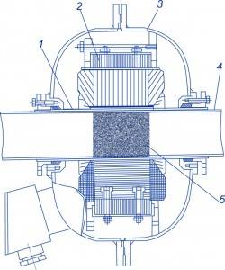
Structure of AVS unit

 Cavitational hardwares are used for creation of oil-fuel, oil-mazut mixtures and emulsions. These emulsions are often used to increase the combustion efficiency or utilization of watered fuels.

 Cavitational process has a great destruction power which can be used for desintegration of solid substances contained in liquids.

 A hard spot crushing is one of the applications of this process which is included to heavy fuels.

 This process is also used in order to increase the caloric content of the heavy fuel oil.

 Cavitation can be used in fuel treatment process. During this treatment fuel obtains additional purification and at the same time fraction ratio is redistributing to the light fraction. The tests of such fuel are demonstrated decreasing of soluble gum amount.

 After treatment by AVS is increasing the quality and caloric content of fuel. As a result we can reach complete fuel burning and decreasing the mass of contaminants. Investigation of cavitation influence on quality of fuel is still urgent and that research is conducted by different private companies and research institutes.

 Cavitational devices can increase hydrocarbon fuel viscosity. As a result necessary heating value is decreasing and at the same time is increased fuel spraying dispersion.

 AVS unit was created as a reactor for large industrial productivity. This ultrasonic generator can be successfully used for:

  • petroleum treatment for pipeline transportation which leads to petroleum viscosity decreasing, destruction of paraffin leads to reduction of the sedimentation on pipe walls;
  • pre-cracking petroleum treatment for the purpose of light fraction yield increase.

Experimental Results: Light fuel product yield increasing

 Experimental researches show the following results:

– cavitational treatment allows increasing the fraction yield at the same volatilization temperature.

 It follows that ultrasonic vibrations accelerate petroleum diffusion in paraffin, intensify the process of paraffin destruction. Acceleration of paraffin dissolution is caused by intensification of oil blending process (on the line oil-paraffin) and influence of pressure surge.

Ultrasonic vortex generators AVS-100. Unit application

 Cavitation technology application

 Cavitational effect is accompanied by microexplosions, ultrasound and also by mechanical cuts and encounters from exposure of the hundred of cuts pairs which are moved towards each other with the high linear speed. The value of that speed is reach to a few dozen of meters per seconds which gives a possibility to cut dispersed matters to the smallest microparticles. In fact it is a micropulse. Per one minute occur hundreds of thousands of micropulses.

 The methods of petroleum and petroleum residues processing are based on phase transition which is typical for dispersed system. An effect on phase transitions kinetics can be achieved by chemical agents and physical fields. As a result the nuclear radius is changed, changed also the thickness of adsorptive solvation sphere of compound recurring unit. This unit is an element of petroleum dispersed system. These processes allow increasing the desired petrochemical products yield, improve their quality and reduce energy consumption.

Light fuel product yield increasing

 The idea of long-chain organic compounds crushing into short-chain which create a new compounds leads to creation of light fuel products is not new. Those researches were started in the 1960s by soviet scientists. But today, at the time of high prices on the petroleum and its processing cost increase, cavitational technologies are particularly topical.

 For today the method of cavitational oil processing is most qualitative. Specific density of light fuel products is increased after cavitational treatment of petroleum.

Vortex Cavitational Hardware

 The main direction of an ultrasonic vortex cavitational generator application (or AVS unit by PC GlobeCore) is petroleum industry.

 Cavitational hardwares are used for creation of oil-fuel, oil-mazut mixtures and emulsions. These emulsions are often used to increase the combustion efficiency or utilization of watered fuels.

 Cavitational process has a great destruction power which can be used for desintegration of solid substances contained in liquids.

 A hard spot crushing is one of the applications of this process which is included to heavy fuels.

 This process is also used in order to increase the caloric content of the heavy fuel oil.

 Cavitation can be used in fuel treatment process. During this treatment fuel obtains additional purification and at the same time fraction ratio is redistributing to the light fraction. The tests of such fuel are demonstrated decreasing of soluble gum amount.

 After treatment by AVS is increasing the quality and caloric content of fuel. As a result we can reach complete fuel burning and decreasing the mass of contaminants. Investigation of cavitation influence on quality of fuel is still urgent and that research is conducted by different private companies and research institutes.

 Cavitational devices can increase hydrocarbon fuel viscosity. As a result necessary heating value is decreasing and at the same time is increased fuel spraying dispersion.

 AVS unit was created as a reactor for large industrial productivity. This ultrasonic generator can be successfully used for:

  • petroleum treatment for pipeline transportation which leads to petroleum viscosity decreasing, destruction of paraffin leads to reduction of the sedimentation on pipe walls;
  • pre-cracking petroleum treatment for the purpose of light fraction yield increase.

Experimental Results: Light fuel product yield increasing

 Experimental researches show the following results:

– cavitational treatment allows increasing the fraction yield at the same volatilization temperature.

 It follows that ultrasonic vibrations accelerate petroleum diffusion in paraffin, intensify the process of paraffin destruction. Acceleration of paraffin dissolution is caused by intensification of oil blending process (on the line oil-paraffin) and influence of pressure surge.

Cavitational technology in wastewater treatment process

Cavitation is one such recent technique which has been found to be substantially beneficial in wastewater treatment.

Cavitation can be described as formation, growth and sub-sequent collapse of cavities releasing large magnitudes of energy locally, creating conditions similar to hot spots, and also generating strong oxidizing conditions by way of production of hydroxyl radicals and also hydrogen peroxide.

cavitation technology for wastewater treatmentThe efficacy of cavitational reactors can be significantly enhanced by combining cavitation with other oxidation processes or by using catalysts and/or additives.
Cavitational reactors can be recommended as pre-treatment methods of waste purification.

By combining conventional and cavitational technologies we can achieve complete purification of industrial wastewaters which contain heavy metal ions, chromium compounds, phenol and also organic and inorganic substances.

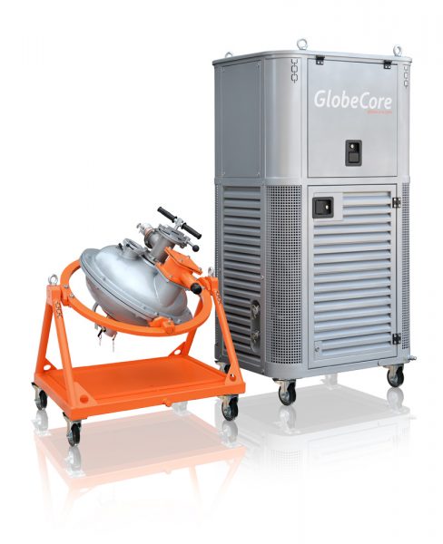
Engineers from PC GlobeCore have used the cavitational principle to design AVS unit or Magnetic Vortex Activator. In cavitating water purification devices the extreme conditions of cavitation can break down pollutants and organic molecules.

The main way of AVS unit application is wastewater treatment. Usage of this unit leads to acceleration of industrial wastewater neutralization, reducing energy and reagents consumption.

Consider the following example “wastewater treatment from phenol and other organic contaminants”.

“Cavitation can be described as formation, growth and sub-sequent collapse of cavities releasing large magnitudes of energy locally, creating conditions similar to hot spots, and also generating strong oxidizing conditions by way of production of hydroxyl radicals and also hydrogen peroxide”.

We have designed new uninterrupted way of wastewater treatment  from phenol and other organic contaminants by means of vortex layer (cavitational process). We tested artificial wastewater by Intensifier of Technological Process AVS. These wastewaters contain similar concentration of phenol, acid and contaminants as real manufacturer’s wastewaters.

Research suggests that Intensifier of Technological Process provides qualitative treatment of wastewater from phenol at lower costs to compare with other known methods.

Conditions of the wastewater treatment by AVS unit from phenol concentration 0.5-10 g/dm3 and acidity of the medium 5 g/dm3 are as follows:

  • oxidizing agents: potassium bichromate (concentration 0.2-5 g/dm3); manganese dioxide (concentration 1.2-10 g/dm3); potassium permanganate (concentration 0.1-1.0 g/dm3);
  • wastewater’s temperature – 20–45 °С;
  • oxidization time – 0.1-2 seconds.

AVS unit industrial process flowsheet is much simpler in technological execution than contemporary industrial process flowsheets.

According to this process flowsheet phenol wastewater enters to equalizing reservoir which is made to blending and equalization of phenol concentration. Wastewater and potassium bichromate (oxidizing agent with concentration 150–300 g/dm3) inject to the unit working chamber by means of pump.

Phenol oxidizes in apparatus from where wastewater injects to another vortex layer machine. In the second stage hexavalent chromium regenerates by ferrous sulfate in alkaline medium and at the same time neutralizes and settle Cr3+. As alkaline agent can be used lime, soda or other reagents.

While wastewater treating from phenol, oxidized another organic impurities. Level of formaldehyde content decreases from 10 g/dm3 to 50-100 mg/dm3, methanol – from 6.4 g/dm3 to 2.3 mg/dm3, diphenylol propane – from 4.6 g/dm3 to 150 mg/dm3.

Following conditions are recommended to decline the wastewater phenol level:

  • Incoming water acidity level – at least equal to 3-5 g/dm3;
  • Wastewater temperature during oxidization  – 45 °С (if the wastewater contains gums, temperature should be increased to 45–60 °С);
  • Oxidizing agent consumption – 2.5-3.0 weight parts for 1 gram of phenol;

AVS unit productivity: for AVS-100 – to 10 m3/h, AVS-150 – to 25 m3/h.

Application of AVS unit permits to:

  • reduce energy consumption in 10-15 times;
  • reduce oxidizing agent consumption in 1.5-2 times
  • reduce the working area of waste treatment facilities in 1.5-2 times

Wastewater treatment from phenol by AVS-100

Water_Wastewater

Qualitative treatment of wastewater from phenol and other organic contaminants has a great practical importance within different branches of industry.

In many cases, contemporary ways of usage by enterprises do not provide high qualitative treatment (degree of phenol decline is 75-90%). These ways have defects such as long process duration from 3 to 5 hours, long processing time, high reagent consumption (pyrolusite, kali bichromate or sodium bichromate), and process temperature is 95–100 °С, bulk equipment, necessity of large working area.

We have designed new uninterrupted way of wastewater treatment from phenol and other organic contaminants by means of vortex layer. We tested artificial wastewater by Intensifier of Technological Process. These wastewaters contain similar concentration of phenol, acid and contaminants as real manufacturer’s wastewaters. Content of wastewater is indicated in the table 1.

Continue reading

Fuel modification by means of water. Application of AVS-100

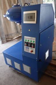
The Intensifier of Technological Process (or AVS-100) can be successfully applied at the fuel industry for liquid hydrocarbon fuels modification by means of water. This unit can be used for production of motor and heating fuels which have improved operational and ecological characteristics.

fuel modified by waterThe mode of obtaining of modified liquid hydrocarbon fuel includes mixing of hydrocarbon components and the water by means of rotate electromagnetic field. Ratio of the hydrocarbon component and water is 60 to 40 and 98 to 2.
 To increase the octane number of blending components we injected oxygenates which was equal to 5-10% of all mass of the hydrocarbon component.

 During less than 10 seconds the mixing components rotate in the electromagnetic field. Fuels obtained by this method allow reaching their complete burning and increase technical and economic parameters.

 A method of obtaining an emulsion fuel, comprising the simultaneous mixing of fuel, water and the stabilizer (surfactant) to maintain the stability of fuel-water emulsions.

 According to this method we mix water and SAA and after that we add to this solution the fuel or we mix fuel, water and stabilizer simultaneously. Injection of the fuel into emulsion proceeds with the ratio of speed and flow equal to the value 1:1:50.

 Main insufficiency of this method is usage of SAA. As a rule, utilization of this component gives negative operational and ecological effects such as carbon deposit on the rings and cylinder, high concentration of CO and CH in the propulsive gas. Besides, this technology is very difficult and insecure. Even small irregularity of proportions of the base components flow speed can destroy emulsion (emulsion become unstable).

 The technical result is increase of economic and operational characteristics of fuels.

 The method includes dispersive water fractionation in the fuel to the size 1 micron by means of fractionation like sieve, or statical, rotary and ultrasonic mixing machine. Obtained emulsified fuel contains emulsified system which includes the one of the compound sorbidol ether.

 By this method modification of the diesel fuel leads to decreasing of the cetane number, to viscosity growth and increasing of the soluble gum content. The fractionation process by means of different types of mixer machine and application of sieves is very difficult. This process performed cyclically to obtaining the droplet of water of desired size.

Intensifier of Technological Process AVS-100. General view

Intensifier of Technological Process AVS-100. General view

At room temperature the time of preserving stability of this emulsion not to exceed three months, that not enough for industrial utilization.

 Relative to above-described method utilization of Intensifier of Technological Process allows obtaining stable antifloating fuels by means of rotate electromagnetic field which is created in the working space of the AVS unit.

 How do we reach this? During 10-15 seconds we mixed the components at the room temperature into the rotate electromagnetic field created by AVS unit. Water content in the hydrocarbon component reaches the value 2-40% of the mass. Obtained by this method water-fuel emulsions are very stable; so you don’t need to use SAA.

 Invention suggests utilize oxygenates as additives which increase octane and cetane numbers. We have used water-soluble oxygenates including spirits (such as ethyl alcohol) and ethers.

 After fuel modification by means of water we have obtained fuel which is fit with all standards but has higher octane number (increased by 2-3 positions). You can see the comparison results of the exhaust gases content before and after modification in the table 1. As you can notice, CO and CH value content is reduced.

 Invention can be implemented by all producers of fuels including producers of heating oil. Application of this unit allows obtaining stable and not peeling liquid hydrocarbon compositions with the water.

 Fuel modified by means of water fits with standards and has higher value of octane number relative to the base sample. Testing of the fuel samples modified by water allows discovering their detergent effect.

 This emulsion permits to reach high total fuel and carbon sediments burning, also increases technical and economic indices of fuels.

 You can reach this result by using The Intensifier of Technological Process and application of ferromagnetic particles.

 Exemplary embodiment

Example 1.

 Reagents processing. The capsule from steel was filled by – 1750 ml of benzine (0.85-0.9 % of volume), – 500±50 g of ferromagnetic particles, – 2-40% of water and 5-20% of oxygenates. This capsule was closed hermetically and processed by Intensifier of Technological Process during 10-15 seconds. As result we obtain a stable water-fuel emulsion which is nonsegregating over a long period of time.

 Application of AVS unit permits to change molecular structure of fuel and water during the mixing process. Blending of water and fuel generates a new chemical compound which cannot be destroyed.

 Water content in the benzine depends on processing condition of hydrocarbon molecule by means of vortex layer. These molecules undergo inside structural changes, also change their physicochemical properties.

Example 2.

In the same way as in the previous example, capsule was filled by 1750 ml of diesel fuel and 3-5% of water.

As result it was obtained the water-fuel emulsion which has high ecological characteristics and high cetane number.

Example 3.

In the same way as in the first example, capsule was filled by black oil. Obtained water-fuel emulsion allows reaching high total fuel and carbon sediments burning, decrease nitric oxide emissions into the atmosphere and also permits to remove difficult and expensive devices for black oil dewatering and cleaning of precipitated water.

Industrial production of fuels by means of Intensifier of Technological Process permits to obtain considerable economical effect by using the water as a fuel and reduce emissions into the atmosphere of pollutants and other substances.

Table 1

№№ sample

Quantity of revolutions per minute

MIL-G-3056C Type 2 (USA)

Benzine modified by water
probe 26

СО, %

CH, ppm

СО, %

CH, ppm

1

Quantity

0,5

490

0,4

400

2

revolutions per minute

0,8

500

0,2

370

3

(trace)

0,9

550

0,1

350

Average value

0,73

497

0,24

374

1

2500-

1,3

190

0,6

180

2

3000

1,25

200

0,1

180

3

revolutions per minute

1,25

200

0,1

180

Average value

1,27

197

0,27

180


Nanomodified Concrete Compositions. New way of the AVS unit application

Syndiotactic polypropene cementThe one of the main problems of contemporary construction material production is problem of obtaining concrete compositions of high quality. The possible way to resolving this problem is modification of a cement stone structure that allows using all durability potential of the crystalline hydrates and also increases the quality of all concrete components. We have investigated the ways of concrete quality improvement by using nanotechnologies and nanomaterials such as magnetic activation.

 Let`s consider the results of application of AVS unit (Intensifier of Technological Process by PC GlobeCore) during the production of fine-grained concrete compositions.

 We have used standard methods to research the durability characteristics and physical and mechanical properties.

 We have made the test of mixing concrete components four times. This was made in order to provide homogenization of concrete components including nanoagents.

 To intensify the process of components mixing in AVS unit we have used ferromagnetic particles covered by polymer coating. In other cases we have investigated the influence of Intensifier of Technological Process on production of magnetic mixing water.

Intensifier of Technological Process AVS-100. General view

Intensifier of Technological Process AVS-100. General view

Solutions of the one composition were made from the same fillers. Mixture ratio of components is 1 to 3. Cement-water factor ranged from 0.6 (for examples which were hydrated by the magnetic water) to 0.8 (for examples which were hydrated by the ordinary water), content of nanoagents ranged from 0.5% to 2%.

Time of water processing by the variable magnetic field is from 2 to 5 seconds.

 Results of test show that even small quantity of carbon nanoparticles and their application increase the complex of properties of concrete.

 The maximum degree of the test sample durability can be obtained by adding of additive agent whom is equal to 1% all batching mass.

 Durability peak is in the range from 0.5% to 1% of nanoagents content in concrete. Interesting that the durability of nanomodified samples exceeds the durability of control samples during compression testing in 5.8 times and during bending test in 5.1 times.

 Results of testing you can see at the below figures.

These figures show that the samples which were made only by using magnetic water have the durability less than 20-25%. So, preparing of the concrete mix by using AVS-100 unit is more qualitative.

But when we added more than 1 % of nanoagents we observed reduction of durability degree during each of compression tests and bending tests.

 As result of our investigations we were conclude that nanoagents have a great impact on the durability values of concrete mixes and processes of concrete structure formation. It is reasonable to suppose that nanomodified concrete will have the best values of durability and longevity.

 Usage of the carbon nano-particles in the concrete production has great prospective future.

 Are you interested in AVS-100?

Construction materials production. Application of the AVS-100 unit

Expanded clay industry

expanded clay In the process of expanded clay production the argillous raw material homogenizes and mills in the drilling mud mixers and rollers. But these equipments not ensure qualitative desintegration. As result we obtain the expanded clay of low quality.
 Insufficiently desintegration and homogenizing of raw materials lead to the result when even 3% of carbonate inclusion in the low-melt expanded clay can make it unusable. Obtained in such way expanded clay lose its durability or destroyed upon storage by the reason of CaO hydration.

 The oversanded glay with free SiO2 content to 10-30% is also not suitable for expanded clay production. All those problems can be successfully resolved by using Vortex Layer Machine – AVS-100 PC GlobeCore production. When we are using the unit AVS-100 for desintegration and homogenizing of the burden material we obtain the expanded clay of general engineering and special designations. In this case we also reduce the volume weight and increase the durability.

 Table 1

Results of desintegration and homogenizing of the burden material for expanded glay production by using AVS-100


№ of  experiment

Raw materials characteristics and treatment duration in AVS-100

Expanded glay mechanical properties

Treatment of the burden material
in AVS

Mixing of the  burden material
out of AVS

Volume weight, γ, g/cm3

Shear strength limit σс*10-5, Pа

strength-density ratio

Volume weight, γ, g/cm3

Shear strength limit σс*10-5, Pа

Strength-density ratio

 1 CaS04 with 26% of free SiO2 content(treatment of  slurry 30 с)

0,24

2,25

10,3

0,38

1,60

5,1

 2 The same with 41% of free SiO2 content(treatment of  slurry 30 с)

0,34

2,45

7,8

0,84

3,24

4,1

 3 hydromicaceous clay (dry treatment 7 min)

0,85

29,4

36

1,6

9,81

6,5

Slip treatment of CaS04 with content of free SiOup to 40% leads to reducing of volume weight of the expanded glay in 2 times and increasing of its durability. The expanded glay strength-density ratio is almost in two times higher in the expanded clay, which is made from the burden material the unit AVS-100. The reason of sharp properties increase of the expanded clay is obviously activation of the high-silica sand caused by creation of active center or other words free radicals creation which are produced by the reason of the bond rupture of Si—O.

Intensifier of Technological Process AVS-100. General view

Intensifier of Technological Process AVS-100. General view

 Activation of SiO2 leads to active participation of the expanded glay in the silication and glass formation. After the expanded glay baking in its granules are absent coarse particles of SiO2, which are the concentrator of tension. Presence of SiO2 in the glass content increases its durability and thermostability.

 Good results are obtained by dry treatment of the raw material by the vortex layer. For example, from the monothermite (hydromicaceous clay) we obtained the light-weight fireproof aggregate which has the volume weight in 2 times lower but the durability in 2 times higher than which we have for the control sample (experiment 3, table 1). The positive result was obtained by dry treatment of the multicomponent burden material (with 50% ashes content) by vortex layer.

 The given examples shows you that the application of AVS-100 (Intensifier of Technological Process) is very perspective for obtaining of the expanded glay of high durability and thermostability from oversanded and over-carbonized materials, burden materials which contain up to 50% of  waste product, for example, the coal ash.

 Cellular concrete production

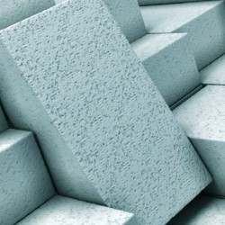
 Cellular concrete Cellular concrete is made in result of solidification preliminarily blown-out mixture of the cementing medium, water, silicious component using gasifier of components. Most frequently as foaming agent used aluminum powder. The aluminum powder reacts with water solution of calcium hydroxide and disengages hydrogen.
 In fact, the quality of cellular concrete is high when the size of pores decreasing and homogeneity of porosity is rising.

 In order to ensure best quality of cellular concrete is necessary to distribute aluminum powder in its weight and increase the degree of dispersion. Besides, the one of technological factors which determines the cellular concrete structure is content of active CaO in mixture.

 As usual the preparation of gasifier reduces to partial paraffin film stripping from aluminum particle surface by mixing of this film with water and surfactant species, after these action need to introduce suspension into solution.

 Because of low efficiency of mixing devices, paraffin film practically not removed.

 In addition, there is a coagulation of aluminum particles, which leads to the local concentration of gas in the products, the appearance of voids and cracks. Because of shortage of gas emission in the case of gas silicate production is necessary to introduce up to 25% of lime into the mixture.

 The necessity of additional introduction of a lime into the mixture is specified by requirement to obtain the durability of concrete which allows to keeps it in vesicular condition by the end of gas emission using the hydration cementation.

 Application of AVS-100 unit for preparation of aluminum powder suspension in production of the gas silicate allows avoiding the coagulation of aluminum particles, raises their activity, gas yield and homogeneity of the mixture. At the table 2 you can see some of the comparative data of physicochemical properties of the gas silicate which was made by using the aluminum suspension fabricated by different methods.

 Table 2

Comparative data of physicochemical properties of the gas silicate which was made by using the aluminum suspension fabricated by different methods

№ of  experiment

Conditions of suspension preparation

Unit  AVS-100 productivity, L/h

Mechanical properties of the gas silicate

Treatment of aluminum silicate suspension by AVS

Preparation of aluminum powder suspension by mixing machine

Volume weight, γ, g/cm3

Shear strength limit σс*10-5, Па

Strength-density ratio

Volume weight, γ, g/cm3

Shear strength limit σс*10-5, Па

Strength-density ratio

1

Aluminum powder – 100%

against the estimated quantity

120

385

377

414

18,7

10,3

11,8

2,56

1,47

1,41

396

419

438

15,2

79,5

10,8

2,03

0,92

1,14

2

The same – 90% against the estimated quantity

950

386

427

375

14,5

15,2

12,3

1,85

1,70

1,80

437

14,1

1,51

 The table shows that usage of treated aluminum suspension by AVS-100 allows to obtaining the gas silicate which has the durability up to 10-30% and quality index up to 20-60% higher in comparison with the control sample (table 2, experiment 1).

 Application of Intensifier of Technological Process gives a possibility to decrease by 10 % gasifier consumption and by 2% lime consumption. At the same time there is no weighting of gasifier. On the contrary, the volume weight of the gas silicate is reduced but its durability is increased. Obviously, the quality of the blown-out concrete can be increased by the treating process by AVS-100 unit in the vortex field of sand-lime mixture or in the sand-cement mixture on purpose of activation of SiO2 like we do the same in expanded-clay aggregate production.


The silica brick production

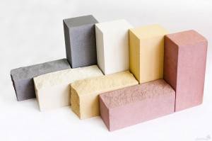
 silica brickThe raw material for the silica brick production is the high-silica sand (92-95% of dry mixture) and the lime (5-8%). Structural capabilities of the brick directly depend from the degree of activation of SiO2 andmixing uniformity of components.

 According to this fact, application of AVS for the treatment of dry mixture by the reason of mixing and activation of components is of the utmost interest. We have investigated the ways of sand-lime mixture activation by spillage of material through the vortex layer of the unit AVS-100.

 It is interesting to note that, in this short-duration treatment of the mixture (mixture particles locate into the vortex field for a fraction of a second) the grinding of the sand and the lime is not observed. The degree of activation can be determined by the changing of mechanical properties of obtained silica brick.

 Table 3

Conditions of the mixture treatment

 by AVS

Compressive resistance

σс*10-5, Pа

Without treatment

91,2

One-time spillage through the layer

239,5

Double spillage through the layer

324,5

Triple spillage through the layer

328,1

 As you can see from the table by the short-duration treatment of the mixture you can increase the durability of the silica brick in 3,5 times.

Obviously, similar processing sand-lime, lime-ash and lime-silica mixtures leads to an marked increase of the mechanical properties of silicate concrete, which are widely used in prefabrication.