Category Archives: News

Wastewater sterilization: completely new method “vortex layer machine”

Wastewater treatment from hexavalent chromium and other heavy metals

The purification and safe disposal (neutralization) of industrial waste water effluents represent a very important ecological problem. The principal problem or requirement involves reducing the concentration of harmful impurities to concentration levels below their maximum allowable concentration limits. In fulfilling this requirement the amount of fresh water consumption needed to maintain the water level in the circulating or recycled water supply system is also reduced, and the operating life of production equipment or lines is concomitantly prolonged as a consequence of decreased corrosion and sediment formation or precipitation (scaling).

In many cases the use of traditional methods, such as settling or sedimentation tanks and ponds, or flotation devices, are not effective or efficient enough for operation, and so more advanced, progressive, and forced methods must be employed, such as treatment by Magnetic Vortex Activator AVS-100 (electromagnetic unit with velocity layer), for instance. The effect of electrophysical factors (electron acceleration, etc.) on contaminated water leads to rapid decomposition of many chemical impurities or contaminants to give inactive (non-harmful) substances.

Designed for last few years electromagnetic units with velocity layer have a wide usage today. These machines can be use by the different branches of industry for intensification of technological (chemical and physical) processes and even for treatment (sterilization, neutralization) of waste water.

From the large quantity of waste water types usually occurs waste water contaminated by chromic compound, fluorine, arsenic, phenol and other harmful and organic impurities. Such waste waters are characterized for the many of machine-building plants.

We have investigated the characteristics of waste water samples before (table 1) and after (table 2) treatment by AVS-100.

Table 1

Characteristics and content of industrial waste water

Parameters

Machine-building plants impurity concentration mg/dm3

food industry

Plants of other sectors

pH effluent

2-6

2-6,5

Cr6+

10-250

20-1000

Fe2+

50-150

10-200

Cu2+

30-120

15-150

Zn2+

20-150

20-170

Ni2+

up to 180

10-190

Cd2+

5-100

15-150

Weighted components

up to 300

up to 350

We have investigated the treatment effectiveness by using Magnetic Vortex Activator AVS-100 from two methods: Ith method – sterilization of chromium-containing wastewater by Cr6+ up to Cr3+ and using the reagent (sulfuric acid iron); IIth – combined neutralization and treatment from the heavy metals ions of chromium-containing wastewater and acid-base wastewater.

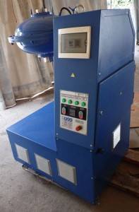
Intensifier of Technological Process AVS-100. General view

Intensifier of Technological Process AVS-100. General view

The process of chromium-containing waste water purification is as follows. The waste waters which contain the specific hexavalent chromium concentration at the rate of 10-15 m3/h from the flow-equalization basin enter the AVS-100. At the same time from the consumption tank by dosing pump to the AVS-100 deliver project quantity of ferrous [iron] sulfate solution (concentration 30-60 g/dm3). At the AVS-100 carry out the waste water treatment by FeSO4 solution, as result occurred regeneration of Cr6+ to the value Cr3+. Completeness of chromium regeneration was verified by the proximate analysis using the diphenilcarbazide and also by the colorimetric method. Sterilized waste waters entered to the neutralization and purification from trivalent chromium. During the research we was changed the consumption of ferrous [iron] sulfate from 80 to 100 % depending of: its stoichiometric consumption; pH environment from 2 to 4 during the regeneration of Cr6+ in the acid environment and from 7,5 to 9,0 in the alkaline condition. To alkalize the wastewaters we used the lime milk solution. Ferromagnetic particles are made from the steel DIN (WNr), mass is 150-250 g, diameter is 2,0-2,5 mm and l/d=10. Duration of treatment at the vortex layer is 0,5-1,5 c. Basic concentration of Cr6+  was changing from 100 to 1000 mg/dm3.

Another sterilization results of chromium-containing waste water by AVS-100

Basic characteristic of waste water

Consumption of FeSO4,
from stoichiometric value, %

Cr6+ content after treatment, mg/l

pH value

Amount of

Cr, mg/l


0,5

460

100

0,5

43

100

0,5

460

90

5

83

100

5

83

90

5

83

80

0,3

0,8

76,5

100

0,8

76,5

90

0,8

2200

100

4

103

100

4

103

90

4,5

1100

100

4,5

1100

90

4,5

1100

80

0,5

The results of industrial testing of AVS-100 show the high quality of treatment from chromium and heavy metals (Fe, Ni, Zn, Cu, Cd) on enterprises which clean chromium-containing wastewater in acid and alkaline conditions. At the same time consumption of reagents in installation AVS-100 is 90-100% of from stoichiometric consumption. Treatment facilities and their operation with using vortex layer of ferromagnetic particles are much simpler and efficient which is confirmed by our experimental investigations. Consumption of reagent such as additive (Ca(OH)2, Na2CO3 in the regular methods of treatment is on level 115-120% and consumption of reducing agent (FeSO4) is on level 150-175%.

Continue reading

Why regenerate transformer oil?

The transformer requires less care compared with other electrical equipment. The degree of maintenance and necessary inspection for its operation depends on its capacity, on the importance within electrical system, the place of installation within the system, on the weather conditions, and the general operating conditions. The normal expected life of a power transformer is about 35-40 years. Life of a power transformer essentially means life of its insulation system comprising mainly: a) Solid dielectric [paper, varnish, cloth, pressboard]; b) Liquid dielectric [mineral oil].

Failure of a transformer in the chain causes interruption in electricity supply and dislocation of all the works going on.

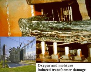
Damage to inside of coil winding stack of oil filled transformer

Damage to inside of coil winding stack of oil filled transformer

Internal causes of failure are

  • failures of transformer insulation,
  • failure of winding due to excessive heating,
  • internal short circuits,
  • failure of winding joints,
  • ingress of moisture in the oil and insulation,
  • deterioration of insulating oil, and
  • failure of other auxiliary internal equipment,

such as reactor of the tap changer, contacts of the tap changer etc. As transformer oil ages, it oxidizes and begins to break down. The by-products of the degradation process include acids, aldehydes, and peroxides, which bind together to form sludge. Sludge attacks the cellulose insulation, inhibits oil flow, and traps heat inside the transformer. Eventually the dielectric gap is bridged, resulting in failure of the transformer.

Oil in addition to serving as insulating means serves to transfer the heat generated in the windings and the core toward the walls of the tank and the radiators. Because of this, it is required that it complies with the following characteristics:

  • High dielectric breakdown
  • Low viscosity
  • Well refined and free of materials that they may corrode the metallic parts
  • Be free of moisture and polar ionic or colloidal contaminants
  • To have a low pour point
  • Low flash point.

The insulating oil (transformer oil) deteriorates gradually with use. The causes are the absorption of the moisture from the air and foreign particles that get into the oil and start to cause oxidation. Oil is oxidized by the contact with the air and this process is accelerated by the increase in the temperature in the transformer and by the contact with metals such as copper, iron, etc.

In addition, the oil suffers a series of chemical reactions such as the decomposition and the polymerization that produces particles that are not dissolved in oil and that are collected in the coil and windings. These particles are called sediments. The sediments do not affect directly the dielectric breakdown, but the deposits that are formed on the winding hinder its normal refrigeration.

Certainly you can change transformer oil (insulation oil) but it`s cannot resolve the problems. Up to 10% of the volume of oil in the transformer is also entrapped in the cellulose insulation; this oil contains polar compounds and can ruin large quantities of new oil.

Changing the oil does not remove all the deposited sludge, especially those in the cooling fins, trapped in the solid insulation and in between the winding.

These residual sludges will dissolve in the new oil and trigger the oxidation process immediately.

Oil purification or degassing is also no longer effective, oil must be other change what the mostly do today or regenerated, what will be a perfect alternative. But you need to remember that regeneration does not replace purification, both of them is very important for transformer maintenance.

The difference between regeneration and purification is that purification cannot remove substances such as acids, aldehides, ketones, etc. in solution, and can therefore not change or improve the colour of the oil.

The regeneration process incorporates the thermo vacuum (purification) and fine filtration processes.

Regenerating the oil or other insulating medium in a transformer is probably one of the few environmentally beneficial alternatives that is also cost and productivity effective at point of delivery and over the lifespan of the equipment.

Regeneration should be the first option to consider in any transformer maintenance program. The aim of a preventative transformer maintenance program is to remove the decay products from the oil before they cause damage to the transformer insulation system. A well-planned preventative maintenance strategy will prevent a wet core condition and ensure that the transformer always operates in the sludge free zone.

First of all, oil regeneration saves a lot of money. Regenerated oil might be better then what you are using now.

It may be noted that reconditioning by centrifugal separator or filtration does not remove the acidity from the oil but will remove only sludge, dust etc. and will tend to retard the process of deterioration. Only regeneration by filters with fuller`s earth will help to reduce the acidity in the used oil and in addition improve the resistivity.

The additional benefit of regeneration is it also works at its most effective whilst the transformer is energized and this also brings the benefit that there is no loss of productivity to the equipment that is fed by the transformer.

We present you a world new product – installation SMM-R (UVR) by PC Globecore. Now you don`t need disconnected transformer because our plant woks with energized transformer, as result – no money loss and no unsatisfied customers.

Today to keep regulators happy and customers and investors interested, you’ve got to demonstrate “green” and environmentally friendly initiatives. Our equipment can resolve this problem. Because in GlobeCore installation SMM-R (UVR) the sorbent that we use “Fuller’s earth” can be reactivated in the same system. Advantage of this technology is that you don’t need utilize exhausted sorbent, but you can use it 2-3 years without replacement. The best process for reclaiming transformer oil is treatment using Fullers Earth.

The Fullers earth can be reactivated 200 to 300 times before replacement is required. Oil can be processed continuously using the same charge of Fullers Earth. No disposal of oil soaked waste is required, greatly reducing the cost of operation.

SMM-R mobile oil regeneration systems are designed for the following processes:

  • Fuller`s earth regeneration of transformer oil;
  • Removal of solved oil decomposition products;
  • Improvement of oil decomposition products;
  • Improvement of oil`s color;
  • Drying electrical equipment while purifying the oil;
  • Removal of moisture from the oil to less than 5 ppm;
  • Filtration with or without heating to 0.5 – 1 micron, (14/12 ISO4406) purity;
  • Degassing to less than 0.1% volumetric gas content;
  • Increase of oil`s breakdown voltage to above 70 kV;
  • Initial filling of electric equipment with insulating oil;
  • Pulling vacuum on transformers and other electrical equipment.

Methods of oil/fuel analysis

Oil/fuel analysis is a series of laboratory tests used to evaluate the condition of lubricants and equipment components. By studying the results of the oil analysis tests, a determination of equipment/component condition can be made.
The inspection or analysis of lubricating oil has been used to check and evaluate the internal condition of oil-lubricated equipment since the beginning of the industrial age. Today, oil analysis programs use modern technology and laboratory instruments to determine equipment condition and lubricant serviceability. Oil analysis uses state of the art equipment and techniques to provide the user with invaluable information leading to greater equipment reliability.
If you understand all aspects of oil analysis you should reap the benefits that many companies get from a well-engineered, reliability-focused oil analysis program.

oil analysis by GlobeCore

There exist a lot of different methods to analyze fuels and oils. For example, there is ASTM in North America or IEC TC10 in worldwide and Europe.

Standard oil analyses include four tests:
Spectral exam:
In the spectral exam, you need take a portion of your oil sample and run it through a machine called a spectrometer. The spectrometer analyzes the oil and tells you the levels of the various metals and additives that are present in the oil. This gives you a gauge of how much your engine is wearing.

Insolubles test:
The insolubles test measures the amount of abrasive solids that are present in the oil. The solids are formed by oil oxidation (when the oil breaks down due to the presence of oxygen, accelerated by heat) and blow-by past the rings. This test tells you how good a job the oil filter is doing, and to what extent the oil has oxidized.

Viscosity test:
The viscosity measures the grade, or thickness, of the oil. Whether it’s supposed to be a 5W/30, 15W/40, or some other grade, we will know (within a range) what the viscosity should be. If your viscosity falls outside that range, there’s probably a reason: the oil could have been overheated or contaminated with fuel, moisture, or coolant.

Flash Point test:
The Flash Point test measures the temperature at which vapors from the oil ignite. For any specific grade of oil, we know what temperature the oil should flash at. If it flashes at or above that level, the oil is not contaminated. If the oil flashes off lower than it should, then it’s probably been contaminated with something. Fuel is the most common contaminant in oil.
Analysis of insulation liquid requires an array of physical and chemical test parameters.

Physical tests Chemical tests Electric tests
interfacial tension,
settling temperature,
viscosity,
color etc.
water content,
acidity,
oxidation of inhibitor and PCB content
dielectric breakdown voltage test,
power factor

Other tests (the most important) also include the following:

DGA gas chromatography test – used for analysis of transformer oil, which helps to diagnose electric equipment condition. The DGA is now a standard in service industry worldwide, and is thought to be the most important test of insulation liquids in electrical equipment. This test is in accordance to ASTM D3612 or IEC 60567.

FID flame ionization detector – used for determine gas concentration, and thermal conductivity detector (TCD). Most of these systems also use methanizer, which transforms any carbon oxide or dioxide into methane and then detects the gas by a very sensitive FID.

Vapor phase method (ASTM D3612C) is a new method, approved about a year ago. This method has been used for dissolved gas analysis for almost a decade. However, the technology has become a standard only several years ago, when Jocelyn Jalbert of Hydro-Quebec improved the vapor phase method using Hewlett Packard instruments (now Agilent Technologies).

The second method involves injection of a certain volume of gas into a clean sealed vacuum vessel. The sample is then sealed and agitated until equilibrium between vapor and gas is reached. After a certain period of time, an automatic sampler removes a part of the gas from the test vessel and injects it into the GC (gas chromatographer). The advantage of the method is that it can be automated, reducing the risk of operator error while handling the sample in the process of preparation and injection.

Liquid chromatography is one of the most dynamically developing analytical methods today. It is used to determine the content of furan derivatives and additives in transformer oil, increasing diagnostic accuracy. Derivatives of the pentatomic heterocyclic compound furan, are selective products of thermochemical destruction and aging of cellulose, which is a component of the oil impregnated paper insulation. The content, dynamic of formation and ratio are the criteria of insulation condition. If more than 15 mg of furan compounds are detected in the oil of operating equipment, regular and extensive monitoring of insulation degradation is required. Furfurol content can also be determined by express analysis, based on color reaction of furfurol with acetic anhydride.

IR-spectrometry (content of Ionol additive) – allows obtaining information on additives, aromatic and acidic compounds content, and can indicate the oil’s type if required. Using IR-spectrometry in combination with high efficiency liquid chromatography facilitates solution of nearly all analytical problems, related to the need of identifying various chemicals in the oil. This can be very important when diagnosing electrical equipment.

Thin-layer chromatography can detect the content of ionol additive. The TLC method is simple and inexpensive in terms of required equipment.

The above shows that modern methods of oil quality control combined with traditional diagnostic methods can significantly increase accuracy and efficiency of complex electric equipment tests.

Transformer oil quality control

It is impossible to ensure reliability and longevity of energy systems without controlling the quality of transformer oil. Recent experience shows that approximately 30% of transformer oil, filled in power transformers, has deteriorated to the point when it becomes a risk factor. This is caused both to natural degradation of oil in operation due to thermal oxidation aging, and contamination with moisture and solid particles. The traditional array of test methods is not quite enough to ensure timely action to prevent the need to replace the oil. The most reliable method of determining the cause for oil aging and selecting the most suitable purification technology is to run a complex test using modern instruments and oil control procedures. Such complex approach to oil quality also allows revealing defects of the equipment in early stages of development.

Transformer oil quality control

 At present, more advanced methods of oil testing are coming into use, such as highly efficient liquid and gas chromatography, automated particle counting and membrane filtration, infrared spectrometry, electric strength measurement etc.

 Electric strength of transformer oil is determined primarily by its purity. Breakdown voltage is significantly affected by dispersed water and solid particles, which conduct electricity.

 The adverse effects of moisture on oil operation have been studied well and wide. However, the effects of particles depending on their size, quantity and origin require further research. Such research is nearly impossible without application of modern oil contamination control systems and instruments. Solid particle content can be determined by the weight methods, which are, however, time consuming and difficult, but do not allow to determine particle size and origin. A much better solution is to use automated particle counters in combination with membrane filtration lab. This allows to control purity class, which describes the dispersed phase in the oil, as per ISO4406.

 Determination of the contamination amount in oil as per ISO4406 is a powerful diagnostic tool, which allows control of not only the purification system’s efficiency, but also presence development of various defects in the electrical equipment. This method is much more informative, precise and quick, compared to the usual weight method.

 As a rule, transformer oils contain a large amount of particles smaller than 10 micron. These particles are very mobile and can drift and concentrate in areas of strong electric field. As a result, field becomes uneven and further degradation of oil insulation reliability follows. Metal particles, apart from reducing electric strength, also increase catalytic influence on the oil’s aging through heat and oxidation. Purity class control allows diagnosing the condition of oil impregnated cellulose insulation of the equipment during operation.

 High efficiency liquid chromatography is one of the most dynamically developing analytical methods today. It is used to determine the content of furan derivatives and additives in transformer oil, increasing diagnostic accuracy. Derivatives of the pentatomic heterocyclic compound furan, are selective products of thermochemical destruction and aging of cellulose, which is a component of the oil impregnated paper insulation. The content, dynamic of formation and ratio are the criteria of insulation condition. If more than 15 mg of furan compounds are detected in the oil of operating equipment, regular and extensive monitoring of insulation degradation is required. Furfurol content can also be determined by express analysis, based on color reaction of furfurol with acetic anhydride.

 Content of Ionol additive is determined by IR-spectrometry; a double-beam spectrometer (Perkin-Elmer 283, Specord M80) can be used. IR-spectrometry allows obtaining information on additives, aromatic and acidic compounds content, and can indicate the oil’s type if required.

 Using IR-spectrometry in combination with high efficiency liquid chromatography facilitates solution of nearly all analytical problems, related to the need of identifying various chemicals in the oil. This can be very important when diagnosing electrical equipment.

 Thin-layer chromatography can detect the content of ionol additive. The TLC method is simple and inexpensive in terms of required equipment.

 Oil quality control can be improved in terms of efficiency and accuracy by determining the dependence of oil’s specific cubic conductance and tg delta on the oil’s temperature. Oil’s aging process results in increased content of polar compounds, acids and peroxides, water etc which leads to formation of colloid structures and sludge. Measuring volume resistivity of the oil, along with other electric tests, such as breakdown voltage and tg delta test increase efficiency of detecting hidden defects of a transformer or its bushings. The difference of volume resistivity between heating and cooling of the oil is common when colloid compounds are present in the oil.

 Implementation of chromatography labs for DGA increases accuracy of diagnostics and makes the analysis simpler and more efficient.

 An example of accuracy and extent of the above methods: a transformer was diagnosed in 1997; the process included a full scale physical and chemical analysis of the oil from the transformer’s tank and bushings.

 DGA indicated CO, CO2 and CH4 exceeding the limits, which is a sign of thermal defects of solid insulation. The high content of furan compounds and their distribution in the oil tank is indicative of paper insulation destruction and local thermal defect. Very large particles of glassine and varnish also indicated destruction of paper insulation and varnish cover of lamination stack.

 Diagnostics of another transformer the same year also yielded extensive results. DGA indicated that oil had been heated to 622C; no defect of the cooling system could have caused such temperatures. A thermographic test showed a possible steel burn-through in the lower portion of the magnetic system between phases A and B. A significant amount of metal particles was detected by membrane filtration.

A closer look at phase B showed, that the bushing’s condition was unsatisfactory. The oil was nearing the limit of contamination content; the membrane filtration method showed presence of regular spherical metal particles in the oil; such particles can only be formed by electric discharge or arc.

 Tg delta was unacceptably high (20%), besides, an abnormal change of Tg delta with temperature was detected (tan delta was 0.5/2.2/20% at 20/70/900C respectively).

 The conclusion of the diagnostic was that the oil aging was accelerated and colloid conglomerates were being formed. Phase B bushing had to be replaced.

 The above shows that modern methods of oil quality control combined with traditional diagnostic methods can significantly increase accuracy and efficiency of complex electric equipment tests.

Intensification of the technological processes by AVS-100: powder industry

The main technological advantage of the powder metallurgy industry is usage of the different metals and its alloy combination, metalloids, metal-to-nonmetal joins and others materials like feed stock for the powder material production. Treatment, mixing, dispersing of those components require a lot of time, energy and material costs. In many cases, usage of vortex layer advantages allow simplify the duration of technological processes of powder preparation and its following treatment.

powder industry GlobeCore

The most typical in this case is the technological processes of high-melting compound production. Those compounds are generally obtained from restoration of transition metal oxide. Formation of the main phase similar to metal occurs by reactive diffusion. This fact imposes stringent requirements to burden material preparation. For example, the size of metals and soot should be fine-dispersed and intimate mixed upon receipt of the carbides (size of the particles should be less than 0.04 mm). All used mills and mixers do not satisfy the requirements of up-dated production. To make the powder with essential granularity apply vibrating sieve sizing by different execution.

Therefore, to obtain the required powders granularity it is using sifting machine with various design vibrosieve. Mixing of burden material compounds spend for a long time to evenly dispense all components. This is necessary operation for obtaining required properties of burden material.

 Table 2

Milling results of the different materials by using the unit AVS-100

Mill material

Filling-in of the operating area of the machine by the mill material, kg

Processing time, minutes

Fractional yield – 56 micrometer, %

Tungsten carbide

2,0

3

95

Zirconium carbide

1,5

3

96

Titanium boride

1,1

2

90

Molybdenum cilicide

2,0

11

52

Titanium carbide

0,8

2

98,5

Molybdenum boride

1,1

2

97,5

Using of the service capacity with the cooling and without it on the units AVS-100 permit to increase the possibility of the installation.

Besides, Intensifier of Technological Processes can be used also for the mixing of metal powder directly before the sintering.

This list of application of the Intensifier of Technological Processes is still incomplete and includes the processes of dispersing, homogenizing, emulsifying etc. Continue reading

On-site regeneration of transformer oil

Regeneration of transformer oil at the transformer’s location is an important preventive measure of transformer servicing.

Transformer life time is, in essence, the life time of its insulation system. The most widely used insulation is liquid insulation (transformer oils) and solid insulation (paper, i.e. cellulose insulation). The oil provides for at least 80% of the electric strength in a transformer. Almost 85% of transformer failures are caused by damaged insulation.

Transformer oil is a good insulator when insulation paper is will impregnated: the oil increases the breakdown voltage of the insulation which it saturates. Low viscosity of the oil allows it to permeate solid insulation and dissipate heat by transferring it to the cooling system. Therefore, liquid insulation is also a cooling liquid. Oxidation stability of the oil allows it to endure high temperatures and prevent significant damage to the insulation system.
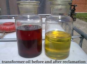
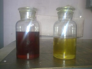
transformer oil after claening

Aging or degradation of transformer oil is usually related to oxidation. As oxygen and water appear in the oil, the oil oxidizes even of other conditions are perfect. Contaminants generated by solid insulations also affect the quality of transformer oil. Reactions which occur in the oil between unstable hydrocarbons, oxygen and other catalyst, such as moisture, with such accelerators as heat, lead to oil decomposition (oxidation).

Heat and moisture, along with oxidation, act as primary accelerators of this process and are the largest threat to solid insulation. If the cooling and insulation system is serviced right, insulation system’s life time can be extended from 40 to 60 years. Unfortunately, oil oxidation cannot be entirely eliminated, however, it can be controlled and slowed by oil treatment. One of the most important transformer maintenance procedures is oil analysis scheduled at least annually. Oil analysis is indicative of the overall insulation condition.

Moisture is a combination of free water, water solved in the products of oil degradation, solved and chemically bound water (it is a part of glucose molecules and is necessary for maintaining the mechanical strength of cellulose). It is impossible to completely dehydrate cellulose insulation.

Transformer oil solves more water at higher temperatures. If the mixture of oil and water is cooled, water will settle out of the oil. The oil will permeate solid insulation, or become bound to oil degradation products. Moisture will distribute itself between the oil and the paper. However, this distribution will be uneven: paper absorbs water from the oil and retains it, in the areas of highest voltage.
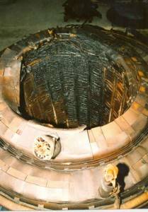
Damage to inside of coil winding stack of oil filled transformer

Damage to inside of coil winding stack of oil filled transformer

Contaminants are formed in the process of transformer operation. Oil decay products are acidic, and they attack cellulose and metals; the acids also create soaps, aldehyde and alcohol, which settle on the insulation, tank walls, breathing and cooling systems in the form of sludge. Sludge forms faster in a heavily loaded, hot transformer operated incorrectly. Sludge increases oil viscosity thus reducing its cooling ability, which has further negative effect on transformer life time.

Contamination also causes insulation to shrink, destroys varnish and cellulose material. It is a conductor for discharges and currents; being hygroscopic, it absorbs moisture and leads to insulation overheating. Sediment forms on the core, which increases transformer temperature.

Cellulose material is the weakest link in the insulation system. Since transformer life time is in essence the life time of its cellulose insulation, and since cellulose degradation is irreversible, contaminants must be removed immediately, until they damage the cellulose. A good maintenance program extends its life time significantly.

Normal servicing of power transformer should attain a practical life time of 50 – 75 years. However, the actual condition of insulation defines the difference of real time operation between 20 – 50 years plus the transformer life time. Experience shows that the most common cause for transformer failure is inadequate servicing and incorrect operation.

Transformer oil can be completely regenerated and made as good as new. Insulation oil can be used indefinitely, if it is processed regularly. The prospect of regenerating a batch of very poor quality oil should be balanced against the relatively high cost of acquiring new oil.

Removal of water and keeping the insulation dry is of utmost importance. Moisture accelerates aging. 1% of moisture in cellulose accelerates aging by one order of magnitude in comparison to 0.1% moisture content.

So, what are the main guidelines for preventive maintenance?

Purification of transformer oil, including regeneration, is a method of extending transformer life time.

The objective of this process is to remove aging product from solid insulation and oil before they damage the insulation system (insulation damage may be determined by furan compounds).

A well planned maintenance strategy aims to avoid accumulation of moisture in insulation and make sure that the transformer always operates in a clean environment.

To stop or slow the aging process of transformer insulation, the oil must be kept in the best possible condition. The following measures will help:

  • Constant control of oil condition;
  • Silica gel in the breather must be in good condition (blue). Never allow more than one third of the silica gel volume to change color to pink;
  • Repair oil leaks as soon as one is detected;
  • Start using an oil purification system for dehydration of oil to 10 ppm at most;
  • Do not add oil contaminated with moisture (if the oil was kept in an open vessel);
  • Start drying the oil as soon as moisture content exceeds 20 ppm or the breakdown voltage drops to below 50 kV;
  • Keep a close eye on the oil’s acidity and regenerate the oil when it reaches the critical level of 0.2 mg KOH/g. Best use a Fuller’s earth system with renewable sorbent (Globecore CMM-R is a good choice);

Sometimes oil should be changed (filtered, rinsed, and refilled). This procedure is best performed on site. Oil is drained form the transformer. The interior of transformer tank is rinsed with hot naphthene or regenerated oil to remove sediment concentrations; then the transformer is filled with regenerated oil.

If the transformer is rinsed only through inspection opening, only approximately 10% of the interior surface will be cleaned. In this case, a film of contaminated oil remains on most of the winding surface and the tank’s interior. Keep in mind that up to 10% of the oil in the transformer permeates cellulose insulation. The oil remaining in the insulation and the transformer contains polarized structures and can poison a large amount of new or regenerated oil.

If the top lid is removed for rinsing, approximately 60% of the interior can be cleaned. Better results can be achieved by using a Fuller’s earth regeneration system, such as GlobeCore’s CMM-R, on a live transformer.

A simple replacement of oil does not remove all sediment, which accumulates in the cooling system and between the windings. This sediment will dissolve in new oil and cause oxidation.

How to regenerate and remove contamination on site

Oil may be regenerated directly in working transformer (prior analysis indicates if such possibility exists, especially the DGA test). The oil is pumped from the tank’s lower valve to the regeneration system, where it is purified, regenerated and degassed before going back to the transformer through the transformer expansion tank. The process continues until the oil is restored and complies with standards or other specifications. If CMM-R unit is used, hot oil is regenerated by percolation through fuller’s earth, then filtration and vacuum degassing and dehydration.

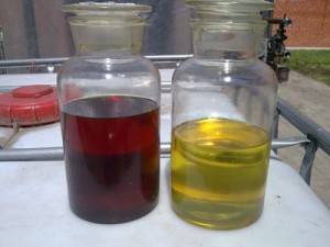
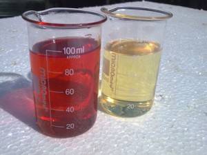
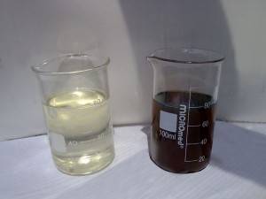
The difference between regeneration and purification is that regular purification cannot remove such things as acids, aldehydes, cetones etc, solved in the oil. Therefore, simple purification cannot change the oil color from dark to light clear yellow. Regeneration, however, incorporates filtration and dehydration.

When regenerating oil, the following results may be expected:

  • Moisture content less than 10 ppm;
  • Acidity below 0.02 mg KOH/g oil;
  • Breakdown voltage of at least 70 kV;
  • IFT at least 40 dynes/cm;
  • Tan delta less than 0.003;
  • Contaminants solved or suspended in the oil are removed;
  • Oxidation stability restored;
  • Oil color changed to clear light yellow;
  • Solid insulation breakdown voltage improved.

Despite the removal of solved or suspended solid contaminants, regular regeneration cannot remove sediment. It is necessary to remove sediment if acidity of the oil is above 0.15 mg KOH/g and IFT is less than 24 dynes/cm. Sludge removal involves circulating hot oil through the transformer. The oil is heated to the point when it becomes a solvent for the sludge. If the transformer is operating, vibrations of the windings enhance the process.

Next to consider is shrinking of insulation and dehydration of transformer oil.

Solid insulation may shrink as a result of motion of loaded coil, specifically, under shock loads; shrinking may become a source of premature failure. Shrinking also comes as a result of cellulose degradation. On-site regeneration of transformer oil does not cause insulation shrinking.

Experience shows that if the transformer insulation is super-dry (up to +2% of dry weight), shrinking does not occur. The regeneration process does not aim to dry transformer insulation. It is impossible to dry the insulation within the time of regeneration. High level of dehydration requires significant time.

Moving moisture from insulation by thermal diffusion is a natural process of restoring the balance between the winding insulation and the oil. The process rate depends on the level of water diffusion through solid insulation.

Removal of sediment from transformer core

Insulation forms and accumulates in cellulose fibers. During purification, the oil is heated to the point when sediment becomes soluble in oil. The process guarantees that the solved contaminants will be removed by regeneration and oil will become clean.

Obviously, regeneration and purification is broader than simple oil restoration.

Loss of furan values

Restoration (regeneration or purification) or replacement of transformer oil destroys furan compounds, which are used to measure the degree of polymerization (insulation condition and life time). Furan analysis should be done before the process.

If transformer oil is allowed to degrade beyond salvaging without regeneration or purification, transformer life time decreases significantly. After purification, a new base line for furan compounds control is established. Future furan test must be referenced against this new base line.

Removal of aromatic compounds

Some types of aromatic compounds may have anti-oxidation properties. Most specifications require that the content of polyaromatic hydrocarbonate be equal or less than 3%. Too much aromatic compounds reduce dielectric or impulse strength and imcrease the oil’s ability to solve most of the solid insulation submerged in oil. Oxidation stability of regenerated oil (after 164 hours at 100 degrees C) was 0.006% by weight, which is lower than the highest allowable level of 0.1% by weight.

Before regeneration is started, the whole system, including the hoses, is filled with oil. Old oil and suspended contaminants accumulated in the bottom of the transformer tank are removed from the lower part of the tank. Regenerated, filtered and pure oil enters the transformer via the expansion tank above. This is done to ensure the level of oil in the transformer is unchanged. The oil freely circulates and the contaminants do not reenter the tank. Only the clean, dehydrated, degassed oil returns to the transformer.

Regeneration is a consistent, somewhat slow process, which solves and removes contaminants from the transformer.

It is important to use only automatic oil heating to keep the oil temperature within limits so as to avoid thermal oxidation and destruction of oil. Using a well designed machine makes the process of transformer oil regeneration safe and economical. However, equipment of lower quality may damage the oil by overheating.

What happens after regeneration

If insulation contains moisture, the level of moisture content on the oil is expected to increase. Moisture will move from insulation to the oil to restore the balance of operation temperature between cellulose and oil. Dielectric strength will fall somewhat with increase of oil moisture content.

If a significant increase of acidity is observed within a short time after regeneration, this is caused by solution of contaminants. This means that the result of regeneration is largely dependant on how long the process takes. Low quality regeneration systems may damage the oil and reduce its oxidation stability, therefore accelerating oil degradation.

Quality of properly regenerated oil is guaranteed for at least two years with consequent purification, if the transformer is well sealed, breather valve and silica gel are serviced in a timely manner, and transformer is operated correctly in terms of load and temperature. A lot depends on the initial quality of oil, insulation type and the environment.

Final testing of the oil after regeneration should include gas and moisture content analysis and breakdown voltage test.

Recommended transformer oil procedures

Regeneration of oil inside or outside of the transformer, while it the transformer is on or off, depends not only on technical parameters, such as gas content etc, but also on economic considerations.

Regeneration is an important part of transformer servicing and should be completed before the oil reaches a critical stage, which may damage solid insulation. If the transformer oil is processed in a timely manner, accumulation of moisture and sludge in solid insulation will be negligible.

Older transformers with very poor quality of oil and insulation (40 years and older) with due point (polymerization degree) below 210, may still be successfully treated while they still operate.

After first regeneration, the transformer will operate well for 5 to 8 yeas. Regular maintenance ensures that in the long run the transformer will only require annual oil test and occasional oil treatment by regeneration.
Transformer oil analysis methods

Transformer oil and solid insulation are subject to natural wear and aging in the process of transformer operation. Therefore, it is imperative that periodic samples be taken for analysis and timely improvement of oil quality, before bad quality oil can cause degradation of insulation. The rate of natural aging and wear degrading insulation materials performance, depends on several factors, such as oil type, system tightness (air tightness), operating temperature, content of water in insulation, as well as amount and type of contamination. Since most transformers in the United States are sealed and do not allow air or water inside, degradation of oil performance may be very slow over many years. Therefore, the oil in many American transformers which have been operated for over 30 years is still in good condition.

oil (1)Schedule of sampling varies depending on type of analysis, significance of equipment, availability of information on malfunction or problem and whether this type of transformer has had certain problems before.
Most of the tests done in North America are based on ASTM methods. In Europe and other countries worldwide, such tests are run according to IEC TC10.

Analysis of insulation liquid requires an array of physical and chemical test parameters.

There are many other tests, but the above are the most important and should be scheduled regularly. The above test allow to assess oil quality, but they do not provide in-depth diagnosis based on operation conditions or equipment health.

Physical tests include interfacial tension, settling temperature, viscosity, color etc. Parameters like water content, acidity, oxidation of inhibitor and PCB content are analyzed chemically. Electric tests include dielectric breakdown voltage test and power factor.

There is, however, a method used for analysis of transformer oil, which helps to diagnose electric equipment condition. This is the DGA gas chromatography test.

Gas chromatography has been used for analysis of gases in petroleum products for decades, although the dissolved gas analysis had not been used for transformer oils until 1970s.

Early on, this method was promoted by Dr. James Morgan of Morgan Schaffer Systems, Canada, and researchers J.E. Dind, R. Daust and J. Regis of Canadian utility Hydro-Quebec. Since the method proved very efficient and provided ample diagnostic information to detect impending malfunctions, it was soon adopted by other labs as well, including Doble Engineering in Massachusetts.

The DGA is now a standard in service industry worldwide, and is thought to be the most important test of insulation liquids in electrical equipment.

Indeed, the ability to detect such a wide range of problems makes this method a powerful tool for both detecting impending malfunctions and determining the cause of such malfunctions.

This test, performed in accordance to ASTM D3612 or IEC 60567, is, at present, the most needed and the most important diagnostic of transformer oil, as insulation degrades from overheating or overloads. Gas is a byproduct of this degradation and can be analyzed to determine the causes and conditions of the malfunction.

Dissolved gases can be detected in low concentrations (at ppm level), which allow timely intervention before electric equipment fails, including repairs during scheduled maintenance.

The DGA method involves extraction or absorption of gases from the oil and injection of these gases into gas chromatographer (GC).

To determine gas concentration, flame ionization detector (FID) and thermal conductivity detector (TCD). Most of these systems also use methanizer, which transforms any carbon oxide or dioxide into methane and then detects the gas by a very sensitive FID.

Extraction of gas from the oil is one of the critical stages of the process. When using the original ASTM D3612A method, it is required that extraction of most gas be made in high vacuum in a sealed glass vessel. Gas is accumulated and measured in a specially graduated tube. Then the gas is removed from the graduated tube through a membrane by a sealed syringe and is immediately injected into the GC. However, that method required the use of mercury. Since at present mercury is not used in most labs due to health hazard, two more mercury free gas extraction methods were developed.

One of these is the direct injection method, described in ASTM D3612B. Gas is extracted form the oil and analyzed within the GC. Initially developed in mid 1980s for this purpose, this method involves injecting oil samples into the chromatographer. When the chromatographer is started, the oil sample passes through a series of valves to the metal sphere of the evaporator. The carrier gas passes through the evaporator and extracts dissolved gas from the oil, which is then carried to the chromatographic column, were it is separated and passed through the sensor. The oil is washed from the surface of the sphere and is purged from the system before the next sample is tested.

Another new method, approved about a year ago, is called the vapor phase method, ASTM D3612C. This method has been used for dissolved gas analysis for almost a decade. However, the technology has become a standard only several years ago, when Jocelyn Jalbert of Hydro-Quebec improved the vapor phase method using Hewlett Packard instruments (now Agilent Technologies). The second method involves injection of a certain volume of gas into a clean sealed vacuum vessel. The sample is then sealed and agitated until equilibrium between vapor and gas is reached. After a certain period of time, an automatic sampler removes a part of the gas from the test vessel and injects it into the GC.

Although the ASTM D3612A has been known for a while, it is still widely used today. The advantage of the method is that it can be automated, reducing the risk of operator error while handling the sample in the process of preparation and injection.

Obviously, each method has its advantages and disadvantages. None of the methods ensures extraction of all gases from the oil. This is related to each gas individual solubility factor, which should be taken into consideration when determining concentration.

The advantage is that oil samples can be taken from most of the equipment without stopping the equipment for maintenance, which helps to reveal potential failures. Nevertheless, the alternative methods, which are more easily automated, are also coming into more use, as they prove their reliability.

To develop standards of gas analysis, laboratories must cooperate with commercial suppliers or prepare standards on their own, since at this time these standards have not been cleared though national standard authorities, such as the NIST.

Repeatability and accuracy of the tests is also very important, as small changes of several ppm may mean the difference between a developing problem which requires immediate attention and a stable parameter which requires no action at all. Efficient sampling process is extremely important to obtaining accurate data from DGA, since such gases as hydrogen or carbon monoxide can easily evaporate form the sample due to their low solubility in oil. To minimize gas losses, ASTM D3613 requires that samples be stored in gas-proof glass or metal vessels.

The typical gases generated by mineral oil and cellulose (paper and cardboard) in transformers are:

  • hydrogen H2;
  • methane CH4;
  • ethane C2H6;
  • ethylene C2H4;
  • acetylene C2H2;
  • carbon monoxide CO;
  • carbon dioxide CO2.

There are always some oxygen and nitrogen present in the oil, and their concentration depends on integrity of transformer sealing. Besides, there are other gases, such as propane, butane, buten, etc, but their content is not usually measured. Gas concentrations are indicative of various types of impending malfunctions and their severity.

For example, four categories of general failures have been described and characterized in table 1

Key gases

Indicate these problems

Methane, ethane, ethylene and some acetylene Heat influencing the oil
Hydrogen, methane and some acetylene and methane Partial discharge
Hydrogen, acetylene and ethylene Arc drawing
Carbon monoxide and dioxide Heat influencing paper insulation

Electric discharges and inefficient cooling of paper insulation lead to the overheating and generation of carbon oxides.

As a rule, transformers retain most of the formed gases, making it possible to make general conclusions regarding insulation wear. Researching relative composition and ratios of the gases may provide more clues. The Rogers or Dornenburg methods are usually used for that purpose.

Severity of the impending failure may be assessed from the total volume of combustible gases (CO, H2, C2H2, C2H4, C2H6, CH4) and the rate of their generation.

Some gases are generated by natural aging of transformer insulation, making it important to discern between normal and excessive quantities of gas. Normal aging or generation of gas depends on transformer design, load and insulation type.

Normally, general indications of gas presence for all transformers are used to detect abnormalities. However, when scheduling new analyses, it is important to consider transformer age and the fact that transformers operated for several years may retain some residual gas.

Actual conclusions on condition of the transformer may be made based on extended gas analysis data. E.g. acetylene requires a lot of energy to form; this gas forms when oil is heated to over 700oC. Excessive oil heating leads to formation of some gas in low concentrations, however, higher concentrations indicate stable arcing, which is a serious operational problem, which will cause transformer failure unless the process is stopped.

The DGA method is an important instrument for detection and analysis of trends and it can be used both as a diagnostic tool, and as a tool to avoid transformer failure. When a large transformer fails, direct losses may be quite high (a transformer may cost over a million US dollars), and the collateral damage may also be significant; profit loss due to blackouts can be the least of the consequences. Transformer replacement, which can take up to one year if the damage is not significant, may cause immense profit loss and fines. However, if the failure is catastrophic, collateral damage is inevitable: it may include damage to nearby transformers, environmental problems due to spilling up to 20000 gallons of oil, or fire.

To avoid this unpleasant scenario, diagnostic of large power transformers should be annual, or at the very least once in three years. As problems are detected, frequency of tests should also be increased.

Insurance companies may also require a certain test schedule. They sometimes require annual oil test to facilitate continuous control.

The following examples illustrate how DGA may be used for detection of existing problems.

Example 1

Transformer information

Transformer oil analysis*

Results

McGrow Edison400 MVA330 kVGas coverMade in 1969 Hydrogen: 7 040 Ethylene was the key gas in this study, which indicated exposure of oil to very high temperature.
Methane: 17 700
Ethane: 4 200
Ethylene: 21 700
Acetylene: 165
Carbon monoxide: 67
Carbon dioxide: 1 040

• 25°C and 760 mm. Hg.

Example 2

Transformer information

Transformer oil analysis*

Results

Delta Star2.5 MVA44 kVRectangular core753 gallons of oilMade in 1991Failed after 4 years of operation Hydrogen: 10900 Ethylene and methane were the key gases. This indicated exposure of transformer oil to high temperatures. Acetylene content was high enough to suggest arcing in the oil. Large amounts of carbon dioxides indicated that paper was also involved in overheating.
Methane: 18400
Ethane: 4440
Ethylene: 24500
Acetylene: 3820
Carbon monoxide: 23800
Carbon dioxide: 36900

• 25°C and 760 mm. Hg.

Example 3

Transformer information

Transformer oil analysis*

Results

Power Hydrogen: 1980 Hydrogen levels were high, indicating a possibility of partial load; high levels of CO and CO2 indicate serious overheating of paper insulation.
11,46 MVA30 kVGas covered500 gallons of oilMade in 1940s Methane: 166
Ethane: 87
Ethylene: 205
Acetylene: 0
Carbon monoxide: 2990
Carbon dioxide: 58300

• 25°C and 760 mm. hg

Example 1

Core fixture was probably lose, and the core was either touching the winding or was very close to it. Undesired main and vortex currents cause local oil overheating.

Example 2.

Probable cause of transformer failure was one phase short circuiting to the ground. This resulted in damage to one of the coils. The analysis showed large acetylene quantity, which indicated possible arcing. The ratio of acetylene to ethylene pointed at oil overheating and/or arcing as possible cause of failure. It is probable that the failure was caused by damage to winding insulation, since relatively high concentrations of carbon monoxide and dioxide indicated insulation material degradation.

Example 3.

A technician notice that the transformer was covered in a cloud of steam in the rain. The test showed that thermal sensor was stuck, and the temperature in the tanks was over 200°C. It was also determined that the transformer was highly overloaded due to disproportion between two phases. The overload was estimated to have lasted for the last two years or so. Inspection of the internal transformer structure showed extensive crumbling and destruction of cellulose insulation. Again, the DGA indicated presence of mostly carbon monoxide and dioxide.

Gas analysis is apparently a very important part of efficiently running electrical equipment. As illustrated by the above examples, the DGA is the most important and efficient diagnostic tool for detection of a wide range of problems.

Methods of fine oil purification

High degree of oil purity is a normal requirement of modern hydraulic and lubrication systems. However, oil manufacturers sometimes fail to ensure the required oil purity, hence the need to purify the oil before operation

One of the instruments of increasing efficiency of energy generation and consumption is reduction of resources consumed for its production with simultaneous increase of production. It is also obvious that new technologies must be implemented by the energy sector to stay competitive. At the same time, reliable energy supply must be secured for the consumers. This requires that all power generation and distribution facilities operate without interruption: all equipment must be kept in good condition.

One of the resources used in the process of generation and distribution is oil. While oil is obviously not a direct means of production, its function is paramount to operation of primary equipment, such as transformers. Primary functions of oil are dissipation of heat and insulation. Oil is considered a resource, since it requires periodic renewal due to gradual contamination. In the process of operation, oil has a tendency to accumulate contaminants of various sizes and origins. This is caused by natural wear of movable parts, oil oxidation and the complex chemical processes inside transformers. The latter cause formation and accumulation of water in the oil; solid insulation of transformers deteriorate over time, releasing products of degradation into the oil; after all, the oil itself ages and degrades, and products of its decay, including additives, forms sludge. As a result, there are numerous types of contamination: oil aging products (decomposed additives), water, corrosion production, silicates, cellulose fibers from insulation, oxidation products, gases, acids etc. Obviously, the contaminants negatively affect functionality of oil filled equipment due to degradation of oil performance, to the point of total equipment failure. Therefore, the significance of oil for efficient and continuous operation of generation and distribution equipment cannot be overemphasized.

Of all solid contaminants, the most dangerous to a transformer are particles smaller than 5 micron, as they constitute approximately 95% of total contamination. Besides, these particles are mostly formed by the products of oil oxidation. These contaminants are charged and have a tendency to accumulate on the internal surfaces of a transformer when the oil reaches a certain level of contamination, hindering release of water from solid insulation and therefore accelerating the process of solid insulation degradation. Contaminants also prevent effective heat exchange between the windings and the oil, and between the oil and heat dissipaters, which increases transformer temperature. The effect is that maximum transformer load is reduced, and oxidation processes are accelerated. The obvious conclusion is oil must be regenerated or purified, as the oil is a costly product; however, the problem of oil replacement exists unchanged to this day. At the same time, industrial liquid purity must be regulated. This issue is appreciated worldwide, hence the internationally accepted standards, such as ISO and NAS. Required purification and regeneration of oil requires special equipment to serve this purpose.

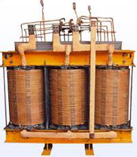
Power transformer winding

Power transformer winding

Since removal of particles larger than 5 micron does not provide required purity, this sort of purification cannot bring the oil condition to below contaminant saturation level. This brings about another problem: not all methods allow removal of contaminants from the internal surfaces of oil filled equipment without stopping the equipment (photo below shows oxidation products attached to the internal surfaces of equipment, including transformer windings). But you can regenerate transformer oil without deenergization only by using our new oil processing equipment.

Particles smaller than 5 micron are mostly oxidation products. These particles are charged, so they have a tendency to stick to the internal surfaces of equipment and form a heat insulating layer hindering heat dissipation; this phenomenon accelerates oxidation exponentially. In transformers, this sludge layer also forms on the windings and prevents release of water from cellulose insulation. Besides, since gaps between windings decrease due to this sludge, the windings may short-circuit, which creates more contamination by breaking oil molecules, and causes loss of power.

Apparently, this problem cannot be ignored, and a solution must be found. One of the possible solutions is electrostatic purification. The idea is to pass the oil through electric field, which will force charged particles to fall out on electrodes (the photo below shows settling of particles in electrostatic cells).

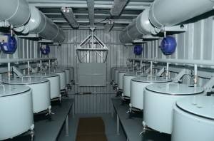
Settling of particles in electrostatic cells

Settling of particles in electrostatic cells

Since this method does not use filters, it does not slow down the oil’s flow rate and does not create pressure buildup. Evidently, small charged particles are removed, which is difficult, if at all possible, to reach by simple filtration. Removing particles larger than approximately 0.1 micron creates a level of purity far from contaminant saturation threshold. Therefore, processed oil will take sediment from the internal surfaces (through diffusion), which will facilitate surface cleaning. Therefore the cyclic nature of this method. However, water, being a conductor, hinders the process. This method is applicable only for oils with moisture content below 500 ppm.

A method which only allows removal of particles larger than 5 micron has no sense. Of course, this sort of filtration might also be useful, but it does nothing to solve the problem, only postponing it. Such filtration can do nothing about the sediment on the internal surfaces of the transformer, whereas industry professionals state that the amount of contaminants and sludge on the surface is 3 – 5 times above that in the oil.

Another operation that has no sense is single-pass filtration. As was mentioned, clean oil has a tendency to accumulate sediment from the internal surfaces of equipment. Therefore, if the oil is only purified once, the problem remains, as the oil will become contaminated immediately after reentering the equipment.

Comparative analysis of oil purity

Comparative analysis of oil purity

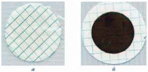
The photo above shows a comparative analysis of oil purity on a 0.8 micron membrane; the left picture shows oil purified to 0.8 micron, the right photo shoes oil filtered to 5 micron.

An important consideration is that when a superimposed field is applied to the oil, it polarizes, since positive charges move in the direction of electric vector, while negative charges move in the opposite direction. As the result, oil molecules acquire dipolar momentum and it polarizes.

Therefore, the use of fine purification equipment at energy facilities is quite necessary, especially after repairs or servicing, while extension of oil life time by 3 or 4 times ensures a significant economic effect.

Transformer oil is both an insulator and a cooling medium; it is in contact with current conducting elements, the cores and solid insulation.

The main methods of maintaining the oil’s functionality are:

  • Constant regeneration of oil by absorbents or thermal siphon filters;
  • Secure sealing of equipment and correct operation of air dehydration filters;
  • Application of special oil anti-oxidation and contamination protection (membrane or nitrogen) or complete sealing of equipment;
  • Constant concentration of anti-oxidation additive (ionol);
  • Efficient cooling of oil;

The aging process occurs at increased temperatures due to combined effects of molecular oxygen on the air, water and electric field. To function effectively as dielectric and heat carrier, and for extension of transformer oil life (which should, ideally, at least match the life time of the equipment), its quality must be monitored.

Comparison of oil before and after purification

A comparative analysis of oils has shown the following results of fine purification:

  • Electric strength increased from 50 to 56 kV;
  • Solved contaminant content decreased from 0.00014% to 0.00001%;
  • Moisture content increased from 18.7 to 23 ppm;
  • No change of other parameters was detected.

Electric strength is the main parameter of insulation oil and defines the oil’s functionality. Electric strength is decreased by moisture content and contamination by solid particles. The described purification process increased breakdown voltage from 50 to 56 kV.

Appearance of solid particles in the oil is indicative of insulation manufacturing defects or wear of materials in the process of operation. Solid particles degrade breakdown voltage.

Solid particle amount on the oil sample before and after purification:

Particle size:               Before             After

5 – 10 micron:            0                      0

10-25 micron:             264                  24

25-50 micron              20                    2

50-100 micron             0                      0

Over 100 micron        0                      0

Apparently, purity was significantly increased. Obviously, the superfine purification process allows purification of oil to any required purity class.

Solved contaminant content is the main criteria for replacement or regeneration of oil.

Solved contaminants subsequently form sediment in the transformer.

Being chemically aggressive and having low heat conductivity, these oil aging products accelerate aging of cellulose insulation and increase dielectric loss. This parameter was improved from 0.00014 to 0.00001 by the superfine purification. Obviously, this method allows significant reduction of solved contaminant content, however, its initial content was far below the acceptable number.

Tangent delta of dielectric materials is the primary indication of their dielectric properties and compatibility of oils for mixing; it also helps to determine degree of aging and the content of various chemical contaminants (construction material degradation products etc.).

Tan delta after overhaul: 0.127, before purification: 0.113, after purification: 0.079.

Acidity is the main indication of the oil’s aging and helps project the oil’s life time; besides, it is the main criterion for replacement of adsorbent in thermal siphon filters and efficiency of regenerating oil with special equipment. Acidity after overhaul was 0.004, before purification: 0.0044, after purification: 0.004.

Flashpoint is indicative of the oil’s composition, and helps detect oil decomposition processes (thermal or electrical). After overhaul: 139, before purification: 139, after purification: 140.

Moisture content in a dielectric is the criteria of its suitability for equipment, and helps determine the cause of declining dielectric qualities of oil and/or solid insulation. Before purification: 18.3; after purification: 23.9 ppm. Moisture content increased after superfine purification, but remained within requirements.

The superfine purification technology does allow to remove solid particles and solved impurities from transformer oil; apparently, this process can positively affect oil performance and life time.

Time to replace your transformer?

There are many transformers out there that were installed before 1990.  A lot of them are nearing the end of their life cycle and the choice of transformer replacement or renovation is a part of any power distribution company’s strategy of maintaining the grid.

Modern oil transformers are not the strongest part of the connection between energy producers and consumers. Transformers have no moving or friction parts, their efficiency of voltage transformation is close to 99%, therefore their life time extends, or rather can be extended well over several decades.

At the same time, unexpected transformer damage may bring about significant repair or replacement expenses, especially if the malfunction is sudden and planned shutdown is not an option.

That is why you need equipment for transformer oil regeneration

That is why you need equipment for transformer oil regeneration

Is there a way to prevent this? Is there a way to know if the transformer is on the verge of failing? How do we understand which processes cause this so as to stop them in time? Let’s start with the last question. The modern oil transformers use oil-saturated thermally stable cellulose to conductor insulation, interlayer and inter-windings insulation and insulation of live parts and the ground within the magnetic cycle. Dry degassed cellulose submerged in oil is the most reliable of insulation materials known today.

It is, however, also the most vulnerable part of transformer insulation, and has been noted as such before. The April 1920 issue of “The Electric Journal” warned that “moisture and high temperature is the biggest threat to reliable insulation”.

Ask a chemical engineer and he/she will call moisture the biggest threat. Ask this same question to an electrical engineer and he/she will reply that high temperature is the only large threat. Both answers are correct. Moisture combined with high temperature destroys insulation. Protection from moisture and overheating is the key to long transformer life.

There are three reasons the moisture is present in insulation:

  1.  residual moisture from inadequate or ineffective drying in the process of transformer manufacturing;
  2. a byproduct of cellulose degradation and
  3. joining with moisture present in transformer oil.

Insulation overheating, one the one hand, to a large degree depends on loading of the transformer, being, so to speak, an external threat. Other overheating sources are degraded convective cooling due to decreased oil flow, cause by clogging of the cooling system channels and reduction of radiator cooling capacity, or loss of oil due to a leak.

Preventive action to extend your transformer life should include the following:

  • regular scheduled servicing, including visual check for oil leaks;
  • logging of temperature and registration of the highest temperature caused by overloads, as indicated by thermometer.

Since in 90% of cases, cellulose decomposition is caused by overheating, it is imperative to check connected loads to prevent new connections and load increase which exceeds the transformer’s nominal power (loading capacity). It has been proved, that temperatures over 140oC caused by overheating, cause gas bubble formation, which in turn decrease insulation dielectric strength, which may lead to short circuiting and premature transformer failure.

If you are relying on additional ventilators or oil pumps for cooling to increase transformer thermal resistance, make sure they can limit insulation temperature to protect it from overheating.

As far as moisture is concerned, measures to reduce its level are taken as far back as when the transformer is design and built. Engineers and producers must eliminate water accumulation around gaskets around the external transformer case to prevent ingress of moisture through loose gaskets.

Oil leaks must be prevented and eliminated with perseverance, since these not only allow oil to escape the transformer and contaminate the environment, but also allow harmful moisture in. This moisture is accumulated in insulation. The same goes for diaphragm of the auxiliary pressure relief device, or, more rarely, for the failure of pressure relief valve to close.

Producers must use a combination of thermal and vacuum dring to reduce residual insulation moisture content during transformer assembly. When the transformer is being assembled, insulation is usually exposed to the environment (dew, condensation, precipitation) and may contain up to 10% water by weight, unless it is thoroughly dehydrated. Just 1% moisture content in the insulation paper accelerates the natural aging and wear of insulation by one order of magnitude. It is generally accepted that the acceptable content of water in newly assembled transformer should fall within 0.3% – 1% by weight. Hence the need to use dry heat, about 100oC, along with 1 – 3 torr vacuum to reduce moisture content in the insulation to 1%.

What are the signs that the transformer must be replaced?

First, if your data indicates that the transformer has been systematically overloaded, it must be replaced with a more powerful one. Continued use of this transformer will lead to damage and malfunction due to overheating, and at the worst possible time, as it goes.

If oil sampling and analysis are not yet a part of your servicing schedule, they should be. Start collecting oil samples and analyze them for moisture content. This, along with measurements of impedance or safety factor of insulation, will give you a good indication of its moisture content. Insulation safety factor of older transformers must not exceed 4% of the initial. The most probable cause of exceeding this threshold is insulation moisture.

Second, you should make a habit of regularly running a full DGA (dissolved gas analysis). When cellulose is submerged into an oil tub and is subjected to high temperature, its performance suffers, which leads to formation of water, acids, carbon dioxide and monoxide. The DGA test will identify several gases which may be indicative of existing problems to pay attention to, but CO2 and/or CO indicate overheating and a possible threat for transformer operation.

Extending transformer lifetime is the one and only most important strategy of energy related companies. Transformers are expected to be reliable and durable.

Twenty or thirty years is a very realistic life time for a transformer. However, if the transformer have been operated incorrectly, including multiple faults, if overloads and leaks have happened before, letting moisture in, its life time can become significantly shorter.

Obviously, transformer replacement is a costly affair; still, such replacement may be even more painful if the transformer fails suddenly and replacement requires an expensive unscheduled power cut. Following the simple advice above will guarantee your transformer a long and productive life.

Why regenerate transformer oil?

The transformer requires less care compared with other electrical equipment. The degree of maintenance and necessary inspection for its operation depends on its capacity, on the importance within electrical system, the place of installation within the system, on the weather conditions, and the general operating conditions. The normal expected life of a power transformer is about 35-40 years. Life of a power transformer essentially means life of its insulation system comprising mainly: a) Solid dielectric [paper, varnish, cloth, pressboard]; b) Liquid dielectric [mineral oil].

Damage-to-inside-of-coil-winding-stack-of-oil-filled-transformer

At the picture you can see the inside damage of coil winding stack of oil filled transformer

Failure of a transformer in the chain causes interruption in electricity supply and dislocation of all the works going on.

Internal causes of failure are failures of transformer insulation, failure of winding due to excessive heating, internal short circuits, failure of winding joints, ingress of moisture in the oil and insulation, deterioration of insulating oil, and failure of other auxiliary internal equipment, such as reactor of the tap changer, contacts of the tap changer etc.As transformer oil ages, it oxidizes and begins to break down. The by-products of the degradation process include acids, aldehydes, and peroxides, which bind together to form sludge. Sludge attacks the cellulose insulation, inhibits oil flow, and traps heat inside the transformer. Eventually the dielectric gap is bridged, resulting in failure of the transformer.

Oil in addition to serving as insulating means serves to transfer the heat generated in the windings and the core toward the walls of the tank and the radiators. Because of this, it is required that it complies with the following characteristics:

  • High dielectric breakdown
  • Low viscosity
  • Well refined and free of materials that they may corrode the metallic parts
  • Be free of moisture and polar ionic or colloidal contaminants
  • To have a low pour point
  • Low flash point.

The insulating oil (transformer oil) deteriorates gradually with use. The causes are the absorption of the moisture from the air and foreign particles that get into the oil and start to cause oxidation. Oil is oxidized by the contact with the air and this process is accelerated by the increase in the temperature in the transformer and by the contact with metals such as copper, iron, etc.

In addition, the oil suffers a series of chemical reactions such as the decomposition and the polymerization that produces particles that are not dissolved in oil and that are collected in the coil and windings. These particles are called sediments. The sediments do not affect directly the dielectric breakdown, but the deposits that are formed on the winding hinder its normal refrigeration.

Certainly you can change transformer oil (insulation oil) but it`s cannot resolve the problems. Up to 10% of the volume of oil in the transformer is also entrapped in the cellulose insulation; this oil contains polar compounds and can ruin large quantities of new oil. Changing the oil does not remove all the deposited sludge, especially those in the cooling fins, trapped in the solid insulation and in between the winding. These residual sludges will dissolve in the new oil and trigger the oxidation process immediately.

Oil purification or degassing is also no longer effective, oil must be other change what the mostly do today or regenerated, what will be a perfect alternative. But you need to remember that regeneration does not replace purification, both of them is very important for transformer maintenance.

The difference between regeneration and purification is that purification cannot remove substances such as acids, aldehides, ketones, etc. in solution, and can therefore not change or improve the colour of the oil. The regeneration process incorporates the thermo vacuum (purification) and fine filtration processes.

Regenerating the oil or other insulating medium in a transformer is probably one of the few environmentally beneficial alternatives that is also cost and productivity effective at point of delivery and over the lifespan of the equipment.

transformer-oil-regeneration-by-Globecore

Regenerated transformer oil by GlobeCore  UVR 450/16 unit

Regeneration should be the first option to consider in any transformer maintenance program. The aim of a preventative transformer maintenance program is to remove the decay products from the oil before they cause damage to the transformer insulation system. A well-planned preventative maintenance strategy will prevent a wet core condition and ensure that the transformer always operates in the sludge free zone.

First of all, oil regeneration saves a lot of money. Regenerated oil might be better then what you are using now.

It may be noted that reconditioning by centrifugal separator or filtration does not remove the acidity from the oil but will remove only sludge, dust etc. and will tend to retard the process of deterioration. Only regeneration by filters with fuller`s earth will help to reduce the acidity in the used oil and in addition improve the resistivity.

The additional benefit of regeneration is it also works at its most effective whilst the transformer is energized and this also brings the benefit that there is no loss of productivity to the equipment that is fed by the transformer.

We present you a world new product – installation SMM-R (UVR) by PC Globecore. Now you don`t need disconnected transformer because our plant woks with energized transformer, as result – no money loss and no unsatisfied customers.

Today to keep regulators happy and customers and investors interested, you’ve got to demonstrate “green” and environmentally friendly initiatives. Our equipment can resolve this problem. Because in GlobeCore installation SMM-R (UVR) the sorbent that we use “Fuller’s earth” can be reactivated in the same system. Advantage of this technology is that you don’t need utilize exhausted sorbent, but you can use it 2-3 years without replacement. The best process for reclaiming transformer oil is treatment using Fullers Earth.

The Fullers earth can be reactivated 200 to 300 times before replacement is required. Oil can be processed continuously using the same charge of Fullers Earth. No disposal of oil soaked waste is required, greatly reducing the cost of operation.

SMM-R mobile oil regeneration systems are designed for the following processes:

  • Fuller`s earth regeneration of transformer oil;
  • Removal of solved oil decomposition products;
  • Improvement of oil decomposition products;
  • Improvement of oil`s color;
  • Drying electrical equipment while purifying the oil;
  • Removal of moisture from the oil to less than 5 ppm;
  • Filtration with or without heating to 0.5 – 1 micron, (14/12 ISO4406) purity;
  • Degassing to less than 0.1% volumetric gas content;
  • Increase of oil`s breakdown voltage to above 70 kV;
  • Initial filling of electric equipment with insulating oil;
  • Pulling vacuum on transformers and other electrical equipment.