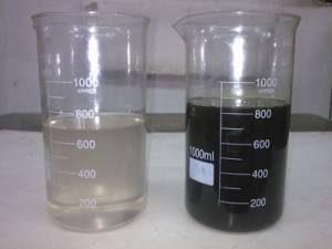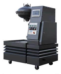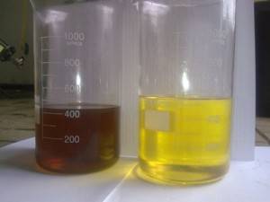
Transformer oil and solid insulation are subject to natural wear and aging in the process of transformer operation. Therefore, it is imperative that periodic samples be taken for analysis and timely improvement of oil quality, before bad quality oil can cause degradation of insulation.
The rate of natural aging and wear degrading insulation materials performance, depends on several factors, such as oil type, system tightness (air tightness), operating temperature, content of water in insulation, as well as amount and type of contamination.
Since most transformers in the United States are sealed and do not allow air or water inside, degradation of oil performance may be very slow over many years. Therefore, the oil in many American transformers which have been operated for over 30 years is still in good condition.
Schedule of sampling varies depending on type of analysis, significance of equipment, availability of information on malfunction or problem and whether this type of transformer has had certain problems before.
Most of the tests done in North America are based on ASTM methods. In Europe and other countries worldwide, such tests are run according to IEC TC10.
Analysis of insulation liquid requires an array of physical and chemical test parameters.
There are many other tests, but the above are the most important and should be scheduled regularly. The above test allow to assess oil quality, but they do not provide in-depth diagnosis based on operation conditions or equipment health.
Physical tests include interfacial tension, settling temperature, viscosity, color etc. Parameters like water content, acidity, oxidation of inhibitor and PCB content are analyzed chemically. Electric tests include dielectric breakdown voltage test and power factor.
There is, however, a method used for analysis of transformer oil, which helps to diagnose electric equipment condition. This is the DGA gas chromatography test.
Gas chromatography has been used for analysis of gases in petroleum products for decades, although the dissolved gas analysis had not been used for transformer oils until 1970s.
Early on, this method was promoted by Dr. James Morgan of Morgan Schaffer Systems, Canada, and researchers J.E. Dind, R. Daust and J. Regis of Canadian utility Hydro-Quebec. Since the method proved very efficient and provided ample diagnostic information to detect impending malfunctions, it was soon adopted by other labs as well, including Doble Engineering in Massachusetts.
The DGA is now a standard in service industry worldwide, and is thought to be the most important test of insulation liquids in electrical equipment.
Indeed, the ability to detect such a wide range of problems makes this method a powerful tool for both detecting impending malfunctions and determining the cause of such malfunctions.
This test, performed in accordance to ASTM D3612 or IEC 60567, is, at present, the most needed and the most important diagnostic of transformer oil, as insulation degrades from overheating or overloads. Gas is a byproduct of this degradation and can be analyzed to determine the causes and conditions of the malfunction.
Dissolved gases can be detected in low concentrations (at ppm level), which allow timely intervention before electric equipment fails, including repairs during scheduled maintenance.
The DGA method involves extraction or absorption of gases from the oil and injection of these gases into gas chromatographer (GC).
To determine gas concentration, flame ionization detector (FID) and thermal conductivity detector (TCD). Most of these systems also use methanizer, which transforms any carbon oxide or dioxide into methane and then detects the gas by a very sensitive FID.
Extraction of gas from the oil is one of the critical stages of the process. When using the original ASTM D3612A method, it is required that extraction of most gas be made in high vacuum in a sealed glass vessel. Gas is accumulated and measured in a specially graduated tube. Then the gas is removed from the graduated tube through a membrane by a sealed syringe and is immediately injected into the GC. However, that method required the use of mercury. Since at present mercury is not used in most labs due to health hazard, two more mercury free gas extraction methods were developed.
One of these is the direct injection method, described in ASTM D3612B. Gas is extracted form the oil and analyzed within the GC. Initially developed in mid 1980s for this purpose, this method involves injecting oil samples into the chromatographer. When the chromatographer is started, the oil sample passes through a series of valves to the metal sphere of the evaporator. The carrier gas passes through the evaporator and extracts dissolved gas from the oil, which is then carried to the chromatographic column, were it is separated and passed through the sensor. The oil is washed from the surface of the sphere and is purged from the system before the next sample is tested.
Another new method, approved about a year ago, is called the vapor phase method, ASTM D3612C. This method has been used for dissolved gas analysis for almost a decade. However, the technology has become a standard only several years ago, when Jocelyn Jalbert of Hydro-Quebec improved the vapor phase method using Hewlett Packard instruments (now Agilent Technologies). The second method involves injection of a certain volume of gas into a clean sealed vacuum vessel. The sample is then sealed and agitated until equilibrium between vapor and gas is reached. After a certain period of time, an automatic sampler removes a part of the gas from the test vessel and injects it into the GC.
Although the ASTM D3612A has been known for a while, it is still widely used today. The advantage of the method is that it can be automated, reducing the risk of operator error while handling the sample in the process of preparation and injection.
Obviously, each method has its advantages and disadvantages. None of the methods ensures extraction of all gases from the oil. This is related to each gas individual solubility factor, which should be taken into consideration when determining concentration.
The advantage is that oil samples can be taken from most of the equipment without stopping the equipment for maintenance, which helps to reveal potential failures. Nevertheless, the alternative methods, which are more easily automated, are also coming into more use, as they prove their reliability.
To develop standards of gas analysis, laboratories must cooperate with commercial suppliers or prepare standards on their own, since at this time these standards have not been cleared though national standard authorities, such as the NIST.
Repeatability and accuracy of the tests is also very important, as small changes of several ppm may mean the difference between a developing problem which requires immediate attention and a stable parameter which requires no action at all. Efficient sampling process is extremely important to obtaining accurate data from DGA, since such gases as hydrogen or carbon monoxide can easily evaporate form the sample due to their low solubility in oil. To minimize gas losses, ASTM D3613 requires that samples be stored in gas-proof glass or metal vessels.
The typical gases generated by mineral oil and cellulose (paper and cardboard) in transformers are:
- hydrogen H2;
- methane CH4;
- ethane C2H6;
- ethylene C2H4;
- acetylene C2H2;
- carbon monoxide CO;
- carbon dioxide CO2.
There are always some oxygen and nitrogen present in the oil, and their concentration depends on integrity of transformer sealing. Besides, there are other gases, such as propane, butane, buten, etc, but their content is not usually measured. Gas concentrations are indicative of various types of impending malfunctions and their severity.
For example, four categories of general failures have been described and characterized in table 1
| Key gases | Indicate these problems |
| Methane, ethane, ethylene and some acetylene | Heat influencing the oil |
| Hydrogen, methane and some acetylene and methane | Partial discharge |
| Hydrogen, acetylene and ethylene | Arc drawing |
| Carbon monoxide and dioxide | Heat influencing paper insulation |
Electric discharges and inefficient cooling of paper insulation lead to the overheating and generation of carbon oxides.
As a rule, transformers retain most of the formed gases, making it possible to make general conclusions regarding insulation wear. Researching relative composition and ratios of the gases may provide more clues. The Rogers or Dornenburg methods are usually used for that purpose.
Severity of the impending failure may be assessed from the total volume of combustible gases (CO, H2, C2H2, C2H4, C2H6, CH4) and the rate of their generation.
Some gases are generated by natural aging of transformer insulation, making it important to discern between normal and excessive quantities of gas. Normal aging or generation of gas depends on transformer design, load and insulation type.
Normally, general indications of gas presence for all transformers are used to detect abnormalities. However, when scheduling new analyses, it is important to consider transformer age and the fact that transformers operated for several years may retain some residual gas.
Actual conclusions on condition of the transformer may be made based on extended gas analysis data. E.g. acetylene requires a lot of energy to form; this gas forms when oil is heated to over 700oC. Excessive oil heating leads to formation of some gas in low concentrations, however, higher concentrations indicate stable arcing, which is a serious operational problem, which will cause transformer failure unless the process is stopped.
The DGA method is an important instrument for detection and analysis of trends and it can be used both as a diagnostic tool, and as a tool to avoid transformer failure. When a large transformer fails, direct losses may be quite high (a transformer may cost over a million US dollars), and the collateral damage may also be significant; profit loss due to blackouts can be the least of the consequences. Transformer replacement, which can take up to one year if the damage is not significant, may cause immense profit loss and fines. However, if the failure is catastrophic, collateral damage is inevitable: it may include damage to nearby transformers, environmental problems due to spilling up to 20000 gallons of oil, or fire.
To avoid this unpleasant scenario, diagnostic of large power transformers should be annual, or at the very least once in three years. As problems are detected, frequency of tests should also be increased.
Insurance companies may also require a certain test schedule. They sometimes require annual oil test to facilitate continuous control.
The following examples illustrate how DGA may be used for detection of existing problems.
Example 1
| Transformer information | Transformer oil analysis* | Results |
| McGrow Edison400 MVA330 kVGas coverMade in 1969 | Hydrogen: 7 040 | Ethylene was the key gas in this study, which indicated exposure of oil to very high temperature. |
| Methane: 17 700 | ||
| Ethane: 4 200 | ||
| Ethylene: 21 700 | ||
| Acetylene: 165 | ||
| Carbon monoxide: 67 | ||
| Carbon dioxide: 1 040 |
• 25°C and 760 mm. Hg.
Example 2
| Transformer information | Transformer oil analysis* | Results |
| Delta Star2.5 MVA44 kVRectangular core753 gallons of oilMade in 1991Failed after 4 years of operation | Hydrogen: 10900 | Ethylene and methane were the key gases. This indicated exposure of transformer oil to high temperatures. Acetylene content was high enough to suggest arcing in the oil. Large amounts of carbon dioxides indicated that paper was also involved in overheating. |
| Methane: 18400 | ||
| Ethane: 4440 | ||
| Ethylene: 24500 | ||
| Acetylene: 3820 | ||
| Carbon monoxide: 23800 | ||
| Carbon dioxide: 36900 |
• 25°C and 760 mm. Hg.
Example 3
| Transformer information | Transformer oil analysis* | Results |
| Power | Hydrogen: 1980 | Hydrogen levels were high, indicating a possibility of partial load; high levels of CO and CO2 indicate serious overheating of paper insulation. |
| 11,46 MVA30 kVGas covered500 gallons of oilMade in 1940s | Methane: 166 | |
| Ethane: 87 | ||
| Ethylene: 205 | ||
| Acetylene: 0 | ||
| Carbon monoxide: 2990 | ||
| Carbon dioxide: 58300 |
• 25°C and 760 mm. hg
Example 1
Core fixture was probably lose, and the core was either touching the winding or was very close to it. Undesired main and vortex currents cause local oil overheating.
Example 2.
Probable cause of transformer failure was one phase short circuiting to the ground. This resulted in damage to one of the coils. The analysis showed large acetylene quantity, which indicated possible arcing. The ratio of acetylene to ethylene pointed at oil overheating and/or arcing as possible cause of failure. It is probable that the failure was caused by damage to winding insulation, since relatively high concentrations of carbon monoxide and dioxide indicated insulation material degradation.
Example 3.
A technician notice that the transformer was covered in a cloud of steam in the rain. The test showed that thermal sensor was stuck, and the temperature in the tanks was over 200°C. It was also determined that the transformer was highly overloaded due to disproportion between two phases. The overload was estimated to have lasted for the last two years or so. Inspection of the internal transformer structure showed extensive crumbling and destruction of cellulose insulation. Again, the DGA indicated presence of mostly carbon monoxide and dioxide.
Gas analysis is apparently a very important part of efficiently running electrical equipment. As illustrated by the above examples, the DGA is the most important and efficient diagnostic tool for detection of a wide range of problems.


