We all talk about priority pollutants, about hazardous substances and discharge to the atmosphere etc. which are dangerous for our environmental. Day by day we adopt new laws and regulations to protect our green future. So, what is that “priority pollutants”? Priority pollutants are highly toxic chemicals. The list of these chemicals is quite large and includes thousands of items but today we will speak about hexavalent chromium and methods of chromium-containing wastewater treatment.
Wastewater which contains chromium and other heavy metals is classified as high toxic wastewater. For this type of wastewater is required qualitative and effective treatment.
Hexavalent Chrome is priority pollutant and exists in several forms. Industrial use of chromium includes in metal alloys such as stainless steel; protective coatings on metal; magnetic tapes; and pigments for paints, cement, paper, rubber, composition floor covering and other materials. Hexavalent chromium can be formed when performing “hot work” such as welding on stainless steel or melting chromium metal.
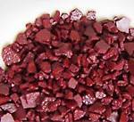
Hexavalent Chromium Compound
Exposure to this chemical is prevalent in different industrial applications. For this reason there exist a lot of international Standards, Directives and Acts which regulate utilization of chromium compounds and obligate to recycle chromium-containing waste. Besides, removal of chrome from wastewater is also needed to achieve the water quality level needed for reuse and recycling.
There are different chromium removal methods such as chemical precipitation, adsorption and biosorption, reverse osmosis, ion exchange, electrodialysis, photo-catalysis. We offer to use breakthrough technology – electromagnetic vortex layer with rotating ferromagnetic particles (AVS-100 or Intensifier of Technological Process).
As we already noted in our previous articles, offered method is very effective and allows reduce reagent consumption in 1.5-2 times, reduce energy consumption is 2 times and decrease working area of treatment facilities in 10-15%.
Let us remember the result of sterilization of chromium-containing wastewater.
The results of sterilization of chromium-containing wastewater by using AVS
|
Basic concentration value Cr6+, mg/dm3
|
pH process
|
Consumption of iron sulfate, % from stoichiometric consumption
|
Ferromagnetic element mass, g
|
Residual Cr6+ content after purification, mg/dm3
|
|
100
|
2
|
100
|
150
|
0
|
|
90
|
0
|
|
80
|
0,56
|
|
100
|
4
|
90
|
150
|
0
|
|
80
|
0,9
|
|
590
|
2
|
100
|
200
|
0
|
|
90
|
0
|
|
80
|
0,8
|
|
1000
|
2,5
|
100
|
200
|
0
|
|
90
|
0,11
|
|
80
|
1,1
|
|
200
|
7,5
|
100
|
150
|
0,012
|
|
200
|
9,0
|
100
|
150
|
0
|
|
90
|
0,05
|
|
80
|
0,98
|
|
750
|
7,5-8,5
|
90
|
200
|
0,1-0,01
|
As you can see from the table, the content of chromium compounds in water tends to zero after treatment by using AVS unit.
The goal of this article is to show how it works. How can we reach the complete purification of wastewater from chromium? So, let`s begin.
Typically wastewater which contains chromium compounds treated in 2 stages. First we need change hexavalent chromium Cr6+ to trivalent chromium Cr3+. As result we need obtain non-toxic materials.
Engineers from PC GlobeCore have investigated the effectiveness of AVS usage in following versions: I – sterilization of chromium-containing wastewater by reduction hexavalent chromium to trivalent chromium, II – combined neutralization of chromium-containing and acid-base wastewater with simultaneous purification from heavy metals ions.
The results of neutralization and purification from heavy metal ions are follows:
|
Basic metal concentration, mg/dm3
|
pH process
|
Consumption of Ca(OH)2, % from stoichiometric consumption
|
Ferromagnetic element mass, g
|
Residual metal content, mg/dm3
|
|
Fe2+;3+= 130,0
|
7,5
|
90,0
|
200,
|
Fe2+;3+ – 0
|
|
Cu2+= 50,0
|
Cu2+ – 0,12
|
|
Zn2+= 45,0
|
Zn2+ – 0,063
|
|
Cd2+= 10,0
|
Cd2+ – 0,07
|
|
Cr3+= 120,0
|
Cr3+ – 0
|
|
Fe2+;3+= 170,0
|
8,5
|
100,0
|
150
|
Fe2+;3+ – 0
|
|
Cu2+= 40,0
|
Cu2+ – 0,018
|
|
Zn2+= 28,0
|
Zn2+ – 0
|
|
Cd2+= 5,5
|
Cd2+ – 0,011
|
|
Cr3+= 100,0
|
Cr3+ – 0
|
|
Fe2+;3+= 250,0
|
8,7
|
100,0
|
200
|
Fe2+;3+ – 0
|
|
Cu2+= 65,0
|
Cu2+ – trace
|
|
Zn2+= 35,0
|
Zn2+ – trace
|
|
Cd2+= 2505
|
Cd2+ – 0
|
|
Cr3+= 350,0
|
Cr3+ – 0
|
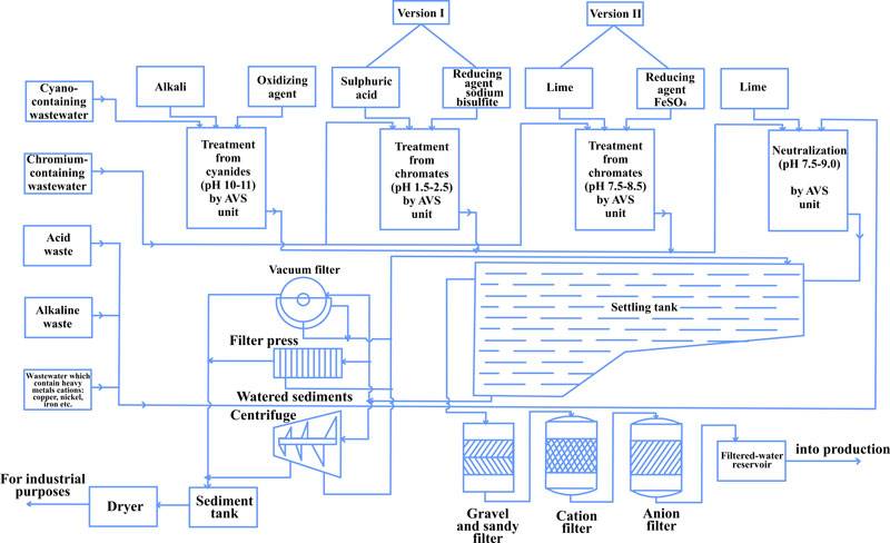
On the basis of performed investigations and production experiments of AVS application for wastewater treatment, we offered and implemented manufacturing schemes of wastewater treatment on different treatment facilities.
On the figure 1 is shown the diagram of simultaneous treatment of chromium-containing and acid-base wastewater.
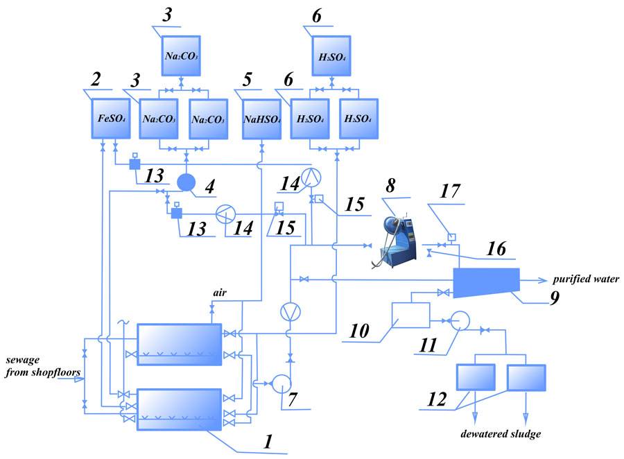
Figure 1. The diagram of simultaneous treatment of chromium-containing and acid-base wastewater:
1 – mixing cylinder; 2 – tank for reducing agent (solution FeSO4); 3 – tank for Na2CO3 solution preparation; 4, 7, 11 – pumps; 5 – tank for reducing agent; 6 – tank for sulphuric acid; 8 – AVS unit, 9, 10 – settling tank; 12 – vacuum filter; 13 – dosing unit; 14 – flow rate meter; 15 – reagent consumption control valve; 16 – sampling unit; 17 – pH-meter
According to this diagram, sewage from shopfloors is alternately entering into two mixing cylinders. When the first of these cylinders is filled by sewage and this sewage is neutralized, to cylinder is fed the acid (in order to acidize the sewage to 2-3 pH level) and is fed reducing agent (sodium bisulfite). After 5-10 minutes mixing this sewage is fed into AVS unit. (Before adding the sewage into AVS, this sewage was filled by Na2CO3 to obtain the value of pH level at elevation 7,5-9). During couple seconds of processing in AVS unit can be achieved complete and effective wastewater treatment by reagents. During this time is completed restoration of Cr6+ to Cr3+ and formation of Cr3+ hydroxide and other heavy metals. As reducing agent can be used FeSO4 (ferrous sulfate).
In this case chromium restoration can be provided in each of acid and base medium. The wastewater with metal hydroxides (after processing in AVS unit) enters the settling tank for defecation and then – the sewerage or the water recycling (to the shopfloors for engineering purpose). The sludge from settling tank is dewatered by vacuum filters.
In conclusion it should be noted that application of AVS unit allows obtaining the quality of treatment lower than maximum permissible concentration, reduce reagent consumption in 1,5-2 times, reduce energy consumption in 2 times and decrease working area of treatment facilities in 10-15%.
We all talk about priority pollutants, about hazardous substances and discharge to the atmosphere etc. which are dangerous for our environmental. Day by day we adopt new laws and regulations to protect our green future. So, what is that “priority pollutants”? Priority pollutants are highly toxic chemicals. The list of these chemicals is quite large and includes thousands of items but today we will speak about hexavalent chromium and methods of chromium-containing wastewater treatment.
Hexavalent Chrome is priority pollutant and exists in several forms. Industrial use of chromium includes in metal alloys such as stainless steel; protective coatings on metal; magnetic tapes; and pigments for paints, cement, paper, rubber, composition floor covering and other materials. Hexavalent chromium can be formed when performing “hot work” such as welding on stainless steel or melting chromium metal.
Hexavalent Chromium Compound
Exposure to this chemical is prevalent in different industrial applications. For this reason there exist a lot of international Standards, Directives and Acts which regulate utilization of chromium compounds and obligate to recycle chromium-containing waste. Besides, removal of chrome from wastewater is also needed to achieve the water quality level needed for reuse and recycling.
Wastewater which contains chromium and other heavy metals is classified as high toxic wastewater. For this type of wastewater is required qualitative and effective treatment.
There are different chromium removal methods such as chemical precipitation, adsorption and biosorption, reverse osmosis, ion exchange, electrodialysis, photo-catalysis. We offer to use breakthrough technology – electromagnetic vortex layer with rotating ferromagnetic particles (AVS-100 or Intensifier of Technological Process).
As we already noted in our previous articles, offered method is very effective and allows reduce reagent consumption in 1.5-2 times, reduce energy consumption is 2 times and decrease working area of treatment facilities in 10-15%.
Let us remember the result of sterilization of chromium-containing wastewater.
The results of sterilization of chromium-containing wastewater by using AVS
|
Basic concentration value Cr6+, mg/dm3
|
pH process
|
Consumption of iron sulfate, % from stoichiometric consumption
|
Ferromagnetic element mass, g
|
Residual Cr6+ content after purification, mg/dm3
|
|
100
|
2
|
100
|
150
|
0
|
|
90
|
0
|
|
80
|
0,56
|
|
100
|
4
|
90
|
150
|
0
|
|
80
|
0,9
|
|
590
|
2
|
100
|
200
|
0
|
|
90
|
0
|
|
80
|
0,8
|
|
1000
|
2,5
|
100
|
200
|
0
|
|
90
|
0,11
|
|
80
|
1,1
|
|
200
|
7,5
|
100
|
150
|
0,012
|
|
200
|
9,0
|
100
|
150
|
0
|
|
90
|
0,05
|
|
80
|
0,98
|
|
750
|
7,5-8,5
|
90
|
200
|
0,1-0,01
|
As you can see from the table, the content of chromium compounds in water tends to zero after treatment by using AVS unit.
The goal of this article is to show how it works. How can we reach the complete purification of wastewater from chromium? So, let`s begin.
Typically wastewater which contains chromium compounds treated in 2 stages. First we need change hexavalent chromium Cr6+ to trivalent chromium Cr3+. As result we need obtain non-toxic materials.
Engineers from PC GlobeCore have investigated the effectiveness of AVS usage in following versions: I – sterilization of chromium-containing wastewater by reduction hexavalent chromium to trivalent chromium, II – combined neutralization of chromium-containing and acid-base wastewater with simultaneous purification from heavy metals ions.
The results of neutralization and purification from heavy metal ions are follows:
|
Basic metal concentration, mg/dm3
|
pH process
|
Consumption of Ca(OH)2, % from stoichiometric consumption
|
Ferromagnetic element mass, g
|
Residual metal content, mg/dm3
|
|
Fe2+;3+= 130,0
|
7,5
|
90,0
|
200,
|
Fe2+;3+ – 0
|
|
Cu2+= 50,0
|
Cu2+ – 0,12
|
|
Zn2+= 45,0
|
Zn2+ – 0,063
|
|
Cd2+= 10,0
|
Cd2+ – 0,07
|
|
Cr3+= 120,0
|
Cr3+ – 0
|
|
Fe2+;3+= 170,0
|
8,5
|
100,0
|
150
|
Fe2+;3+ – 0
|
|
Cu2+= 40,0
|
Cu2+ – 0,018
|
|
Zn2+= 28,0
|
Zn2+ – 0
|
|
Cd2+= 5,5
|
Cd2+ – 0,011
|
|
Cr3+= 100,0
|
Cr3+ – 0
|
|
Fe2+;3+= 250,0
|
8,7
|
100,0
|
200
|
Fe2+;3+ – 0
|
|
Cu2+= 65,0
|
Cu2+ – trace
|
|
Zn2+= 35,0
|
Zn2+ – trace
|
|
Cd2+= 2505
|
Cd2+ – 0
|
|
Cr3+= 350,0
|
Cr3+ – 0
|
On the basis of performed investigations and production experiments of AVS application for wastewater treatment, we offered and implemented manufacturing schemes of wastewater treatment on different treatment facilities.
On the figure 1 is shown the diagram of simultaneous treatment of chromium-containing and acid-base wastewater.
Figure 1. The diagram of simultaneous treatment of chromium-containing and acid-base wastewater:
1 – mixing cylinder; 2 – tank for reducing agent (solution FeSO4); 3 – tank for Na2CO3 solution preparation; 4, 7, 11 – pumps; 5 – tank for reducing agent; 6 – tank for sulphuric acid; 8 – AVS unit, 9, 10 – settling tank; 12 – vacuum filter; 13 – dosing unit; 14 – flow rate meter; 15 – reagent consumption control valve; 16 – sampling unit; 17 – pH-meter
According to this diagram, sewage from shopfloors is alternately entering into two mixing cylinders. When the first of these cylinders is filled by sewage and this sewage is neutralized, to cylinder is fed the acid (in order to acidize the sewage to 2-3 pH level) and is fed reducing agent (sodium bisulfite). After 5-10 minutes mixing this sewage is fed into AVS unit. (Before adding the sewage into AVS, this sewage was filled by Na2CO3 to obtain the value of pH level at elevation 7,5-9). During couple seconds of processing in AVS unit can be achieved complete and effective wastewater treatment by reagents. During this time is completed restoration of Cr6+ to Cr3+ and formation of Cr3+ hydroxide and other heavy metals. As reducing agent can be used FeSO4 (ferrous sulfate).
In this case chromium restoration can be provided in each of acid and base medium. The wastewater with metal hydroxides (after processing in AVS unit) enters the settling tank for defecation and then – the sewerage or the water recycling (to the shopfloors for engineering purpose). The sludge from settling tank is dewatered by vacuum filters.
In conclusion it should be noted that application of AVS unit allows obtaining the quality of treatment lower than maximum permissible concentration, reduce reagent consumption in 1,5-2 times, reduce energy consumption in 2 times and decrease working area of treatment facilities in 10-15%.
 Industrial oil has a lot of advantages which include long lifetime (without adding of antioxidizing additives – from 3 to 10 years); continuous working and protection of industrial systems. So the question concerning using other type of oil arises not frequently. Other advantage of industrial oil is reasonable price; also this oil is not so aggressive for environmental, industrial oil not produce the burned gas or other wastes which pollute the atmosphere.
 How many tons of used oil recycling machine are disposed every year? How many damages we bring to our environmental? Stop throw out your profit into wastes, start recycling and you will obtain the benefits.
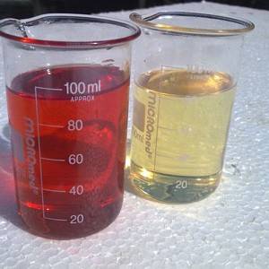
 GlobeCore’s Oil Regeneration (Reclamation) Units are “Two-in-One” industrial systems that not only Purify used and/or contaminated oil, but completely Regenerate/Reclaim the used oil and restore used oil to its original new condition.
 To activate particle surface of extender (for example, soot) it can be exposed to the grinding by ball or vibrating mills. But this processing way is labour-intensive and gives marginal effect. Most effective way is chemical modification of the extender.
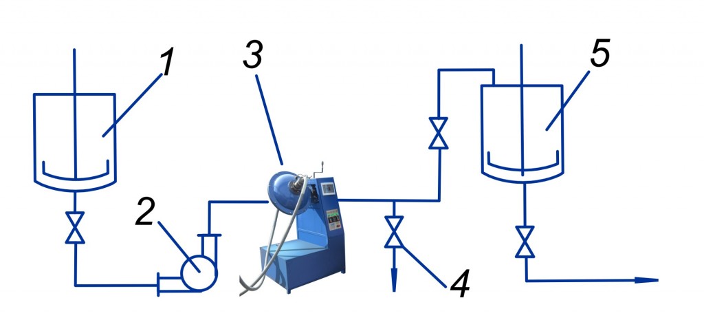
 Water treatment from slight fluorine concentration is extremely important. These difficulties are concerned with chemical particularities of fluorine compounds. As is well-known, the substantial dissolubility has only alkali metal salts of fluoride, potassium, and ammonium.