Category Archives: Useful

SILICONE OIL RECYCLING UNIT CMM-1.0

We are all used to associating power transformers with transformer oil. But in the modern world, electrical companies widely utilize silicone oil as an alternative to mineral based fluids. This is not surprising, considering silicone oil benefits and advantages:

Silicone Fluid (or Polydimethylsiloxane silicone oil) features:

  •  higher dielectric strength and temperature stability,
  • low toxicity, low vapor pressure, low viscosity change
  •  higher resistance to oxidation and chemical inertness

The above make silicone transformer fluid much safer environmentally as well.

On the other hand, operating conditions and power transformer lifecycle can cause some issues:

  1. When arc discharges occur, silicone oil may release harmful gases under the influence of high temperature
  2. High oil viscosity may have a negative impact on transformer heat exchange, reducing circulation of the oil.
  3. Silicone oil is harder to dispose of, combustion of silicone oil causes release of harmful gases.

GlobeCore engineers insist that one process can address the issues above — Silicone Oil Recycling.

Our team has developed a new machine for Silicone Dielectric Oil Regeneration.

Its great advantages are compact size and efficiency.

Silicone Oil Recycler Specifications

Parameter Value
1 Processing capacity, m3/h:

– drying mode

– pumping mode

1.0

1.0

2 Maximum oil output temperature in heating mode, °С 60
  3* Treated oil parameters (at initial moisture content of no more than 50 ppm):

– maximum moisture content by weight , ppm

– filtration fineness, micron

10.0

5

4 Oil output head, m 20
5 Input pressure, MPa, no more than 0.1
6 Oil heater power, kW, 25,2
7 Oil heater mean surface power, kW/cm2, no more than 1.1
8 Nominal power consumption, kW 28
9 Three-phase AC @ 50 Hz, V 380
10 Maximum dimensions, mm

– length (without trailer)

– width (without trailer)

– height (without trailer)

3800 (1300)

2100 (800)

2100 (1550)

11 Maximum weight (without trailer), kg 860 (540)

Note   * With initial oil parameters as follows:

– moisture content by weight – no more than 0.005% (50 ppm)

– oil heating temperature up to +60±5 oС within 30 minutes of heating;

– gas content – no more than 10%

– dimensions may vary

The unit is used during installation, maintenance and operation of oil-filled high voltage equipment (power transformers, high-voltage switchgear, etc.).

The station is assembled in a frame structure with closing doors. Its components are: a vacuum column (VC), a control panel (CP), pumps (P1 and P2), vacuum pump (VP), pre-filter, coarse (F1) and fine filter (F2), piping with valves.

General view of the station is shown in figure 1.

Figure 1 – CMM-1 general view.

Mesh filter MF (figure 2) is installed at the input of the unit to remove mechanical impurities from the oil. Filtration rating of the filter is defined by 200 micron brass mesh, installed in the casing. For filter element cleaning, extract the filter from the input manifold and wash it in clean transformer oil.

Pumps Р1 and Р2 (Fig.1) facilitate input and output of transformer oil. The pumps are controlled from the control panel. P1 and P2 pumps are equipped with by-pass line and valves MV7 and MV8.

Cartridge filters F1 and F2 (figure 1) filter the oil with 25 and 5 micron filtration fineness respectively.

Principle of operation

Flow diagram

Figure 2 shows the unit’s flow diagram.

Figure 2. Flow diagram

The unit can operate in two modes:

1. Pumping and filtration (Flt);

2. Thermovacuum drying (Dry).

Call today+493021788825 or e-mail us to [email protected]

ELECTRICAL TRANSFORMER REPAIR

ELECTRICAL TRANSFORMER ELECTRICAL TRANSFORMER

THE GLOBECORE PROCESS
TO MAINTAIN ELECTRICAL TRANSFORMER OIL IN GOOD CONDITION

Problem #1: Moisture in transformer oil

Nature of Problem: Transformer oil readily absorbs moisture from the air. This water decreases dielectric strength of the oil

GlobeCore Solution: CMM Oil Purification Plant is designed for thermo-vacuum drying, filtration and removal of solid impurities from dielectric insulating oils with a viscosity of no more than 70 cSt at 50°С.  The plant offers purification to class 9 from initial purity class 13 (contaminant content below 0.004%) in multiple passes of the product through the filter section. The Plant is available in different configurations and capacities.

CMM 0.5

Processing rate 0.5 – m3/hour

CMM-2.2

Capacity 2.2  m3/hour

CMM-4.0

Capacity 4 m3/hour

 power transformer repair unit electricl transformer repair unit power transformer repair plant
Perfect solution for small electrical transformers
Conventional 220 electrical outlet power capability
The unit is compact, protected with metal doors, can be trailer mounted for on  field use Perfectly fit for heating electrical transformer and other equipment that contains dielectric insulating oil with hot oil

Problem #2: Moisture in Solid Insulation

Nature of Problem: Insulating paper absorbs and retains moisture due to higher affinity of water to paper than to oil. Moisture in oil-paper insulation can cause electrical transformer failures because (1) it decreases dielectric strength, (2) it accelerates cellulose aging (depolymerization) and (3) it causes emission of gas bubbles at high temperatures.

GlobeCore Solution: Vacuum Cold Trap is connected to Electrical Transformer and vacuum pumps bring the pressure down to 26 Pa. Cooling of the evaporator in the low temperature trap to minus 70oC, causes pressure difference of water vapor above the surface of the solid insulation in the transformer tank and in the body of the cold trap. This difference is the driving force of water evacuation.

The unit is available in stock.

Vacuum Cold Trap

Processing rate is 27×3=81  Pa, liters/second, min

solid isulation maintenance machine
The vacuum cold trap is designed for pulling vacuum and drying of solid insulation of power transformers with voltages 110-1150kV during installation, service and repair

Problem #3: Transformer Oil Oxidation

Nature of Problem: The reaction between unstable hydrocarbons in the oil, oxygen and other catalysts such as moisture, with additional factors such as heat, results in accumulation of decay products in the oil (oxidation by-products). Once oil oxidation starts, the oxidation products themselves act as catalysts to accelerate the oxidation reaction.

GlobeCore Solution: CMM-R and UVR units are designed for Complete Oil Restoration (of dielectric strength and chemical composition). The main operating principle of those units is percolation of oil through a stable sorbent layer. The CMM-R plant operates with Fuller’s earth and the UVR unit uses a special GlobeCore sorbent. All together, the systems remove acids, water and contaminants from insulating oil and insulating paper/windings of an electrical transformer. Those units are very Environmentally Friendly, as exhausted sorbent can be reactivated and used again in up to 300 cycles.

CMM-R2

Processing rate 100 – l/hour

CMM-R24

Capacity 6000  l/hour

UVR 450/16

Capacity 100-1000 l/hour

Transformer oil bleaching machine
The unique feature of the CMM-R unit is the capability to regenerate insulation oil directly in an electrical transformer ·                Energized transformer oil processing; and

·                Automatic Sorbent Reactivation

·                Trailer mounted


The unit successfully processes dielectric transformer oil, turbine oil, industrial oil, heavy fuel oil, and Diesel fuel


Problem #4: Dissolved gas and/or decay products

Nature of Problem: During its lifetime, the transformer generates decomposition gases, essentially from the organic insulation, under the influence of various stresses, both normal and abnormal, which could lead to failure if ignored.

GlobeCore Solution: The UVM unit is designed for degassing, drying, removal of solid particles and heating of transformer oil used in power transformers up to 1150V.
The unit can process mineral oils with the following properties:

Dynamic viscosity, mm2/sec, at 50 °С                    2…12;

Density at 20°С, kg/m3                                           800…950;

Moisture content, ppm, max                                    100;

Purity class ISO 4406, at least                                -/19/16

The UVM unit is available in different design configurations, Zeolite Filtration Section CP-260 is available as an option.

CMM-UVM 4/7

Processing rate 4 – m3/hour

CMM-UVM 10/15

Capacity 8 m3/hour

MCU ZEOLITE OIL DRYING UNIT

Capacity from 1.5 to 4.0 m3/hour

Transformer oil degassing unit Insulating oil degassing machine Zeolite drying system
The UVM unit is designed for:

·         Vacuumizing transformers;

·         Removal of solid particulate matter;

·         Removal of water;

·         Removal of gases

The unit is placed on a tandem axle trailer that is street legal and ready to be towed to any remote  location  This unit is designed to significantly reduce acid levels in used insulating oil

ELECTRICAL TRANSFORMER REPAIR

ELECTRICAL TRANSFORMER ELECTRICAL TRANSFORMER

THE GLOBECORE PROCESS
TO MAINTAIN ELECTRICAL TRANSFORMER OIL IN GOOD CONDITION

Nature of Problem: Transformer oil readily absorbs moisture from the air. This water decreases dielectric strength of the oil

GlobeCore Solution: CMM Oil Purification Plant is designed for thermo-vacuum drying, filtration and removal of solid impurities from dielectric insulating oils with a viscosity of no more than 70 cSt at 50°С.  The plant offers purification to class 9 from initial purity class 13 (contaminant content below 0.004%) in multiple passes of the product through the filter section. The Plant is available in different configurations and capacities.

CMM 0.5

Processing rate 0.5 – m3/hour

CMM-2.2

Capacity 2.2  m3/hour

CMM-4.0

Capacity 4 m3/hour

  electricl transformer repair unit
Perfect solution for small electrical transformers
Conventional 220 electrical outlet power capability
The unit is compact, protected with metal doors, can be trailer mounted for on  field use Perfectly fit for heating electrical transformer and other equipment that contains dielectric insulating oil with hot oil

Problem #2: Moisture in Solid Insulation

Nature of Problem: Insulating paper absorbs and retains moisture due to higher affinity of water to paper than to oil. Moisture in oil-paper insulation can cause electrical transformer failures because (1) it decreases dielectric strength, (2) it accelerates cellulose aging (depolymerization) and (3) it causes emission of gas bubbles at high temperatures.

GlobeCore Solution: Vacuum Cold Trap is connected to Electrical Transformer and vacuum pumps bring the pressure down to 26 Pa. Cooling of the evaporator in the low temperature trap to minus 70oC, causes pressure difference of water vapor above the surface of the solid insulation in the transformer tank and in the body of the cold trap. This difference is the driving force of water evacuation.

The unit is available in stock.

Vacuum Cold Trap

Processing rate is 27×3=81  Pa, liters/second, min

The vacuum cold trap is designed for pulling vacuum and drying of solid insulation of power transformers with voltages 110-1150kV during installation, service and repair

Problem #3: Transformer Oil Oxidation

Nature of Problem: The reaction between unstable hydrocarbons in the oil, oxygen and other catalysts such as moisture, with additional factors such as heat, results in accumulation of decay products in the oil (oxidation by-products). Once oil oxidation starts, the oxidation products themselves act as catalysts to accelerate the oxidation reaction.

GlobeCore Solution: CMM-R and UVR units are designed for Complete Oil Restoration (of dielectric strength and chemical composition). The main operating principle of those units is percolation of oil through a stable sorbent layer. The CMM-R plant operates with Fuller’s earth and the UVR unit uses a special GlobeCore sorbent. All together, the systems remove acids, water and contaminants from insulating oil and insulating paper/windings of an electrical transformer. Those units are very Environmentally Friendly, as exhausted sorbent can be reactivated and used again in up to 300 cycles.

CMM-R2

Processing rate 100 – l/hour

CMM-R24

Capacity 6000  l/hour

UVR 450/16

Capacity 100-1000 l/hour

The unique feature of the CMM-R unit is the capability to regenerate insulation oil directly in an electrical transformer ·                Energized transformer oil processing; and

·                Automatic Sorbent Reactivation

·                Trailer mounted

The unit successfully processes dielectric transformer oil, turbine oil, industrial oil, heavy fuel oil, and Diesel fuel


Problem #4: Dissolved gas and/or decay products

Nature of Problem: During its lifetime, the transformer generates decomposition gases, essentially from the organic insulation, under the influence of various stresses, both normal and abnormal, which could lead to failure if ignored.

GlobeCore Solution: The UVM unit is designed for degassing, drying, removal of solid particles and heating of transformer oil used in power transformers up to 1150V.
The unit can process mineral oils with the following properties:

Dynamic viscosity, mm2/sec, at 50 °С                    2…12;

Density at 20°С, kg/m3                                           800…950;

Moisture content, ppm, max                                    100;

Purity class ISO 4406, at least                                -/19/16

The UVM unit is available in different design configurations, Zeolite Filtration Section CP-260 is available as an option.

​​

CMM-UVM 4/7

Processing rate 4 – m3/hour

CMM-UVM 10/15

Capacity 8 m3/hour

MCU ZEOLITE OIL DRYING UNIT

Capacity from 1.5 to 4.0 m3/hour

Zeolite drying system
The UVM unit is designed for:

·         Vacuumizing transformers;

·         Removal of solid particulate matter;

·         Removal of water;

·         Removal of gases

The unit is placed on a tandem axle trailer that is street legal and ready to be towed to any remote  location  This unit is designed to significantly reduce acid levels in used insulating oil

Individual Approach to Oil Recovery

Transformer oil – is a main isolator in transformer. In addition, it serves as a coolant. It entirely stabilizes electrical breakdown of transformer.

However, its indispensability is dangerous – transformer oil is influenced by moisture and temperature, dissolved gases and various harmful particles that are accumulated in the process of aging. The oil also reacts with the hard materials of transformer, dissolving them in the process.

The main problem is that changing old oil to new one does not produce the desired effect in stabilizing work of transformer. It is impossible to completely remove the old oil from the transformer. A remaining contaminated residue on details and isolation contributes to more rapid aging of new oil.

Due to the fact that outdated oil, containing excess moisture and gases, is recognized as internal pollutant, it is filtered through filtration systems.

GlobeCore is one of the leaders in global market of advanced technologies and specializes in various oil systems.

Different UVR models of oil recovery, by GlobeCore, are universal installations of vacuum oil recycling intended for: cleaning, clarification, removal of aromatics from various oils: transformer oil, turbine oil, furnace fuel, dark diesel, gas condensate, and all types of industrial oils.

Installation UVR is universal and is intended for regeneration as a turbine, transformer and other oils.

Fuel, oil vacuum cleaning system UVR restores original properties of oils which received a dose of negative impurities during previous operation. Such systems are of great interest for energy companies and companies engaged in servicing power transformer equipment, repair of transformers, transformer substations, power plants and hydroelectric turbines, plants for processing and production of oil, tank farms, due to the fact that the mobile unit is connected directly to transformer providing oil cleaning, removing harmful particles from the transformer insulation, as well as operating in online transformer.

Fuel, oil cleaning system UVR by GlobeCore provides the highest level of oil recycling and oil reclamation and recovery during production and storage. After the full cycle of regeneration and filtration the oil is stable and less susceptible to oxidation, respectively, does not darken and does not gain an odd odor. According to these characteristics, after regeneration the service life of oil increases and at the same time the productivity of transformer increases too.

Many enterprises produce and mix their own fuel to achieve maximum efficiency of the engines. They use systems for mixing and blending. And the final stage is the UVR plant which regenerates (cleans) oil, acquires stability and complies with international standards.

GlobeCore has a large list of products in stock. However, in recent years customized installations, systems assembled and adjusted to meet the wishes and requirements of each client are widely popular.  Especially popular features are mobility, complete or partial automation, remote control, different types of climatic performance. Production models can be purchased directly from GlobeCore warehouse. Models of individual design are designed and manufactured to order within 30 to 45 working days.

The equipment is set into operation within one or two days. Readjustment of equipment is not required. The plant can be delivered to any country in the world as agreed with the customer.

Widespread use of fuel, oil cleaning systems UVR make them an integral part of the process at virtually every industrial enterprise.

Removal of Heavy Metals from Wastewater Generated at Electroplating Workshops

We discuss Electroplating Wastewater Treatment in this article.

At the beginning of the twenty first century, the urgency of solving the issues of global environmental problems significantly increased. Today, humanity has almost come to the point where further ignoring of the need to preserve the Earth’s ecosystem will be very costly for future generations.  There are many global environmental problems and each of them deserves attention.  This article will discuss the protection of the hydrosphere from all forms of pollution.

As a result of human activities, industrial wastewater is constantly being generated all over the world. The draining of industrial wastewater into open waters without the proper treatment can lead to irreparable consequences for the environment.  The situation becomes more complicated each day by the fact that industries are developing rapidly and the amount of wastewater increases proportionally to the increases in the size and scope of modern human industries.

According to the World Health Organization (WHO), human diseases caused by the consumption of contaminated water and food can be as high as 80% of the total number of health problems reported each year.  Treatment of industrial wastewaters therefore, is one of the most urgent and priority tasks faced by modern man.

General Characteristics of the Electroplating Industry   

The Electroplating Industry got its name from an electrochemical method of applying mechanical and chemical coatings on various materials to impart hardness and wear resistance as well as anti-corrosion protection and protective-decorative properties.

The electroplating industry can perform galvanizing, chemical passivation of stainless steel, anodizing of aluminum, chemical oxidation of aluminum and steel.  The generation of wastewater is due to the need for washing parts in the process of preparation and applying the electroplate coatings.

Composition of Wastewater Generated from Electroplating Facilities

The composition of wastewater generated from the electroplating industry typically includes washing waters (diluted effluents) and concentrated solutions (pickling, washing, degreasing, chrom- and cyano-containing electrolytes).

The greatest damage to the environment is made by metal compounds that are washed out in wastewater from the electroplating industry.  For example, cyano-containing effluents contain free sodium cyanide (potassium), complex cyanide salt of zinc, cadmium, copper and other metals, as well as salts of alkali and alkaline earth metals.  The concentration of cyanide can range between 5 and 300 mg/l with an acidity level that exceeds the  “7” mark.

Wastewater from Electroplating facilities using chromium contain hexavalent and trivalent chromium, ions of metal, copper, nickel, zinc and sulfuric acid.

Cadmium compounds, even in relatively small quantities, have a dramatic negative impact on fish and other inhabitants of fresh and saltwater resources.  Other negative effects of heavy metals are also well-studied.  They can enter the human body through food and water and can cause the pathogenesis of liver disease, heart disease, brain cancers, and even tumors.

Existing Methods of Treating Wastewater from Electroplating

The main objective of galvanic wastewater production treatment is to reduce the content of heavy metals to the maximum allowable concentrations.  This allows you either to dump purified water into a sewer system, or return it back to use in production.

Since electroplating effluents contain a wide range of heavy metals, each of which requires a different disposition, you will have to resort to a multi-step treatment plan.  Dissolved heavy metal ions must be converted into insoluble chemical compounds, followed by separating and dewatering solids.  In general, the purification process consists of the following stages:

  1. Neutralization – A process that is necessary for the chemical disposition of metals. It comprises of setting the pH level to a certain value using sodium and calcium hydroxides;
  2. Flocculation – formation of macro floccules by the addition of organic flocculants;
  3. Precipitation – separation of the solid phase.  At this stage sludge is also de-watered; and
  4. Polishing filtration by means of ion exchange or sorption.

Despite of all the achievements, ion exchange, reagent and coagulation methods do not fully address the issue of effective and economic efficient cleaning. Besides this, when using these methods of wastewater treatment for removing heavy metal ions, a so-called galvanic slime is formed.  These substances can not be placed in landfill sites designed for solid wastes.  Burial of galvanic slime requires the use of special landfills.  The number special landfills is very small.  Most businesses generating galvanic slime materials therefore, have to store such waste on its own property by creating temporary sludge storage areas.

Ion-exchange and reagent purification methods, using conventional equipment, are very time-consuming.  The reagents are costly, have a greater metal content, and are characterized by the need for expensive and cumbersome equipment.

Use of Vortex Layer Devices in the Process of Purifying
Wastewater Generated by Electroplating Facilities

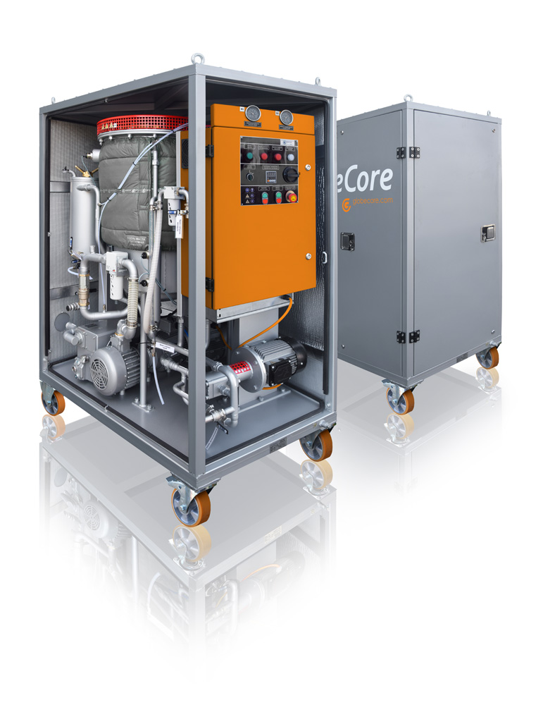
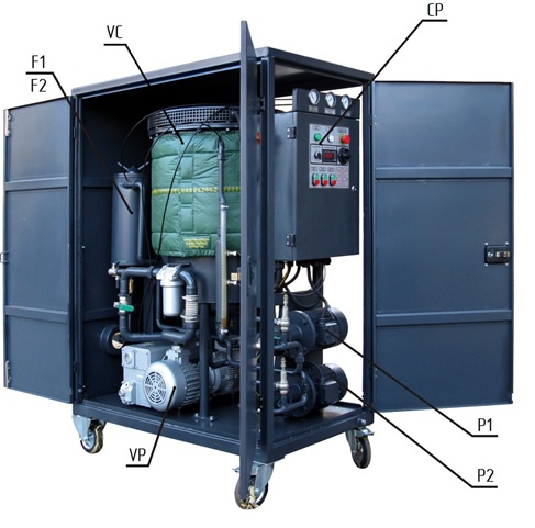
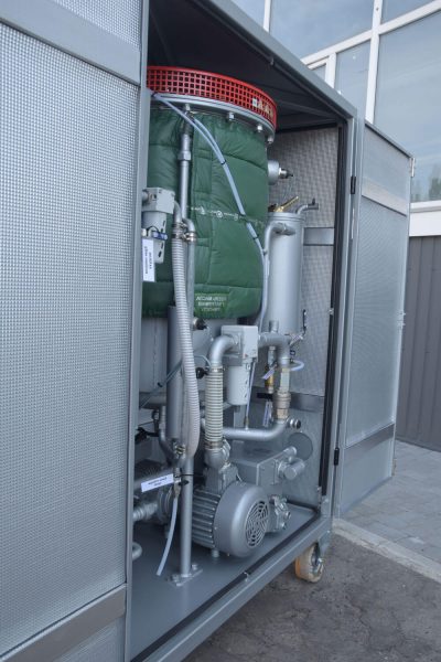
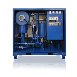
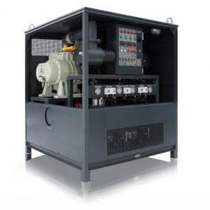
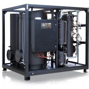
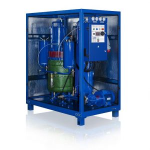
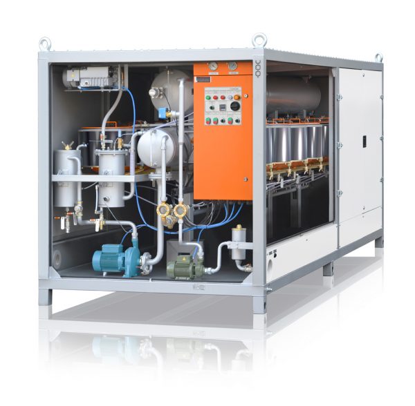
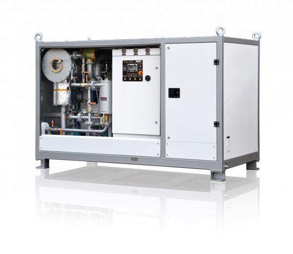
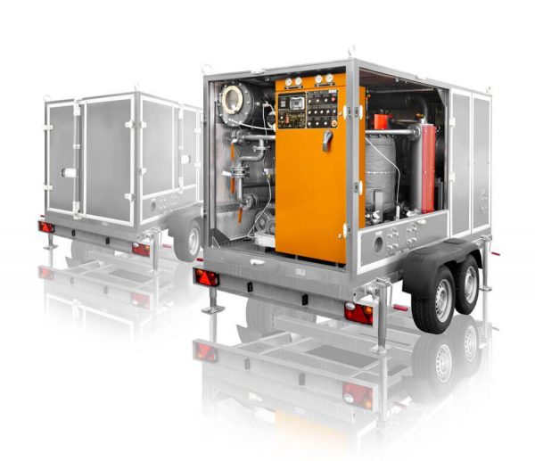
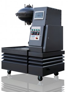
Given the aforementioned, it can be argued that the search for new and more effective approaches to the problem of wastewater treatment in the electroplating industry is highly relevant.  GlobeCore manufactures a modern and effective vortex layer devices.  Today, in a variety of industries there are many successful production lines equipped with such GlobeCore devices.

When analyzing the intensifying factors that occur in a vortex layer device, it can be assumed that the process of wastewater treatment will be subjected to a significant impact from:

  • electrochemical factors, electromagnetic treatment, and activation of substances in the vortex layer;
  • phase dispersing; and
  • geometrical parameters of the operational mode of the vortex layer, and its hydrodynamic factors that provide intensive mixing of the processed media.

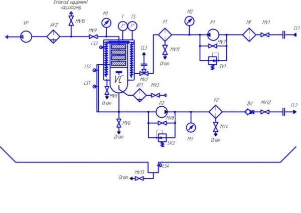
We have carried out studies on electroplating wastewater treatment that remove heavy metals using a GlobeCore AVS-100 type (laboratory) vortex layer device.  As the reducing agent, we used sulfuric acid iron FeSO4.  Recovery of the trivalent and hexavalent chromium at the expense of the reagent was carried out in an alkaline medium for which milk of lime Ca(OH)2 was introduced into the water.

Because the alkaline medium of iron hydroxide additionally acts as a reducing agent, there is no need for acidification drains.  The 0.5 liters of water intended for cleaning had a 10 mg of 10% solution of ferrous sulphate added to it.

For treatment included the use of ferromagnetic particles with a length of 20 mm and a diameter of 1.8 mm with a total weight of 200 grams.  The treatment time made lasted three seconds.

Table 1 below shows the results of the electroplating wastewater treatment process that removed heavy metals using a GlobeCore Magnetic Mill AVS-100 vortex layer device.  The table also contains comparison data obtained with reference values and concentration limits valid for the countries of the European Union.

Table 1

Results of the Electroplating Wastewater Treatment Process Removing Heavy Metals Using a GlobeCore AVS-100 Magnetic Mill

No

Parameter name

Parameter value

Maximum allowable concentration  (European Union)

before treatment

after treatment

1 рН 1.75 6.74 6.5-8.5
2 Fe, mg/l 9.7 2.77 2-20
3 Cu, mg/l 18.29 0.65 0.1-4
4 Ni, mg/l 5.8 <0.02 (not found) 0.5-3
5 Cr+6, mg/l 19.08 <0.005 (not found) 0.1-0.5

The following conclusions can be made about Electroplating Wastewater Treatment:

1) Use of the GlobeCore AVS-100 type vortex layer device in the process of electroplating wastewater treatment will effectively reduce the concentration of heavy metals to values ​​not exceeding the maximum permissible concentrations in the European Union.  The results showed a complete absence of nickel and hexavalent chromium in the treated water.  This shows that the use of the vortex layer devices in countries where there are more stringent requirements for concentrations of hexavalent chromium and nickel will be very popular.

2) Purification of water is instantaneous and does not require the overuse of reagents.

3) The process of sediment settling is achieved much faster than when using agitators.

Grinding of Coal to a Pulverized State

Today, a significant amount of the energy generated and consumed around the world is produced by burning fossil fuels.  In addition to oil and natural gas, coal  is also quite actively used as an energy source.

At modern electric power plants, solid fuels are ground into a pulverized state and, in an admixture with air, are fed into a combustion chamber for burning.  This is preceded by the preparation of large pieces of wet coal, which includes coarse crushing of coal into pieces the size of a few of millimeters.   It is subsequently dried and ground into a pulverized state.

The main advantage of using pulverized coal is the substantial increase in the surface reaction.  This improves the combustion conditions and increases the efficiency of the burners.  Additionally, the use of pulverized coal does not limit the power of the boiler’s combustion conditions.  It allows the operator to fully mechanize the combustion process and makes it easier to control.

There are also alternative ways of using pulverized coal for energy.  First of all, we are talking about co-firing of coal with biomass and preparation of coal-water fuel.

At thermal power plants operating in Europe and North America, co-combustion of coal with wood pellets has been increasingly practiced in recent years.  Such innovation has been able to reduce harmful emissions when burning coal alone.  There are several possible options for co-burning of coal and biomass:

  • the parallel incineration;
  • indirect co-incineration; and
  • direct co-incineration.

In direct co-burning, the coal and biomass are prepared, crushed and fed into the boiler at the same time.  Indirect co-burning is characterized by separate preparation of the coal and the pulverized biomass.  In parallel co-burning, coal and biomass are combusted using separate boilers.

Another option for reducing the amount of harmful emissions is the use of coal-water slurries (coal-water fuels).  They are characterized by low combustion temperature, thereby reducing the nitrogen oxide emissions by as much as 70%.

Existing Methods of Coal Grinding

In practice, special devices, called mills, are used for the grinding of coal.  Ball pulverizer mills can grind and dry soft fuels with a high humidity content at the same time.  They can grind coal to the pulverized state, but have the disadvantages of bulkiness and complexity, as well as a high rate of electricity consumption.

Ball and roller mills are not very effective when processing objects of high strength and/or hardness.  This is reflected in the slow deterioration of crushing capabilities whereby a steady increase in the proportion of large pieces and reduction of the discharge of dust.

There are also difficulties in grinding wet ash coals that merge and become compressed under the grinding elements.  This results in poor milling.

Hammer mills enable simultaneous grinding and drying of fuel using air or a gas-air mixture.  The main drawback of such devices however, is a relatively rapid wear of the beaters (hammers) and the need to replace them after 300 to 600 hours of work.

What does GlobeCore offer?

All known methods of coal grinding are characterized by the complexity and bulkiness of the equipment and the large amounts of energy used.  Vortex layer devices structurally resemble an asynchronous motor.  The main difference is the absence of a rotor.  The device is powered by a three-phase network that generates a rotating electromagnetic field of industrial strength frequency.  The processed material is fed into the working zone where special ferromagnetic particles are added into the material being processed.  The latter begin to rotate under the influence of the magnetic field performing multiple striking impacts on the processed material.

АВЭП
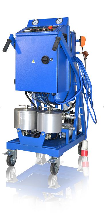
Here at GlobeCore, we have carried out studies on the possibility of grinding coal to a pulverized state using the GlobeCore AVS-100 type vortex layer device.  During the study, a 250 gram piece of anthracite coal was used to test the AVS-100 vortex layer device.  We used ferromagnetic particles with a diameter of 3mm.  As a result, we managed to succeed in crushing the coal to a pulverized state within one and one half minutes.

The results obtained during the experiments suggest that grinding coal by the vortex layer devices takes significantly less time and energy than the known mechanical grinding processes.

GlobeCore is able to manufacture vortex layer devices on a commercial scale through specific customized orders. This equipment can be used in the following systems:

  • preparation of fuel for powdered combustion;
  • preparation of coal-water fuel; and
  • co-burning of coal and biomass.

Using GlobeCore’s vortex layer devices, you can design and implement a completely new system and/or upgrade existing ones.

Design, Manufacture and Installation of Wastewater Treatment Systems on the Basis of Vortex Layer Devices

Each year the world produces about one trillion cubic meters of wastewater.  Approximately one fifth of which receives no treatment before being discharged back into water sources.

The greatest threat to the world’s water supply is posed by industrial effluents resulting from activities in the chemical, food, machine-building, instrument-making, petrochemical, and radiochemical industries.  Wastewater discharged into rivers and other bodies of water is extremely dangerous.  This is due to the fact that:

  1. the overall regeneration process of water in the hydrosphere is much slower than air in the atmosphere; and
  2. the natural processes occurring in an aqueous environment are more susceptible to contamination.

Additionally, water is far more important for the sustenance of the Earth than the analogous processes in the atmosphere.  The feasibility of wastewater treatment therefore, is not in doubt.  The main problems that arise in dealing with this issue relate to the complexity of physical and chemical changes that occur in the process of purification.

Today’s existing ion exchange, reagent, and coagulation methods of industrial wastewater treatment to remove chromium and other heavy metals, do not fully guarantee the efficient and economical cleaning of water resources.  The main drawback of these methods is the formation of large quantities of waste requiring disposal.

When cleaning wastewater, there is a large amount of precipitation formed.   After dehydration, it is usually stored on site at the industrial plants in areas designated for storage.  On site storage makes it necessary to have extra storage spaces that are not always available due to space limitations.

Ion exchange and reagent methods of wastewater treatment using conventional equipment are quite time-consuming, slow, and consume huge amounts of reagents adding greatly to operating costs.

vortex wastewater treatment

GlobeCore offers an alternative approach to wastewater treatment that involves the use of vortex layer devices.  These devices are used in many industries for intensification of physical and chemical processes.  Improving the efficiency of wastewater treatment processes in a vortex wastewater treatment layer device is achieved by the following factors:

  • electrochemical processes, electromagnetic treatment and activation of the substances in the vortex layer;
  • phase dispersion; and by
  • geometrical parameters and modes of operation of the vortex wastewater treatment, its hydrodynamic factors, that provide intensive mixing of the processed media.

For example, when cleaning wastewater and removing phenol with the GlobeCore AVS-100 type vortex layer device, energy costs are reduced by 10 to 15 times.  Reagent consumption is reduced by 1.5 to 2 times.

GlobeCore offers:

a comprehensive analysis of the chemical and bacteriological composition of the wastewater of your enterprise, definition of peak surges and identifying their causes;

  • a custom design of wastewater treatment systems, including computerized systems for management;
  • manufacture of treatment systems on the basis of vortex layer devices;
  • installation and commissioning at your facility; and
  • carrying out all testing.

To receive an expert advice or make an order of wastewater treatment systems, please contact us at one of the contacts.

Application of Vortex Layer Devices for Improving the Quality of Marine Fuels

The first time the possible use of water, in the feed system of internal combustion engines was discussed, took place in the late nineteenth century.  Since then, there have been many studies on the effectiveness of the approach of adding water to fuels.  A couple of known benefits to adding water to fuels include:

  1. intensifies the fuel combustion process; and
  2. reduces the release of incomplete combustion products and nitrogen oxides with the exhaust gases into the atmosphere.

The quality of water used for water-fuel emulsions has a direct impact on the wear of the fuel system’s internal parts.  The most promising systems for obtaining water-fuel mixtures therefore, are those which process not only fuel, but also the water before mixing.  A vortex layer device can successfully perform this task since it causes the complete dispersion of these components.

Structurally, vortex layer devices consist of a tube of non-magnetic material.  Inside the tube there is a rotating electromagnetic field that reacts with with ferromagnetic particles.  The latter are found in the vortex motion.  In the workspace of such devices, there are a number of effects that make possible the deformation of crystal lattice solids, and sharply increase in the reactivity of chemical agents.

Vortex layer devices can input into base fuels up to 7% water.  Mixing actually takes place at the molecular level.  That is why the resulting product is resistant to delamination and can be stored for at least 5 to 6 months.

Another advantage of the use of vortex layer devices is the generation of a large amount of heat during operation.  The vortex layer can be used for the initial fuel and water pre-heating block.

It should be mentioned that the technology for the production of water-fuel emulsions by means of vortex layer devices can be used not only for marine fuels, but in the fuel conditioning systems at boiler plants as well.

You must pay attention however, to the following fact.  During operation of the device, collisions of ferromagnetic particles occurs.  This leads to their gradual abrasion.  The presence of metal particles in marine fuels and in boiler fuels is unacceptable therefore, you need to use the special magnetic traps to remove any unwanted metal particles from remaining in the fuel.

GlobeCore offers magnetic flow metal traps that are made specifically for use in water-fuel emulsions preparation lines equipped with the AVS-100 or AVS-150 type vortex layer devices.  At the Customer’s request, it is possible to produce magnetic metal traps of the required sizes for most other industries.

Anhydrite Binder Production by the Vortex Layer Machine

Introduction

Today’s modern alabaster industry produces products based on alabaster binding materials.  Such products are obtained by burning natural material at low temperatures to obtain hemihydrate of calcium sulfate.  It is worth noting that fired and non-fired alabaster binders are rarely used in this process.  This is due to the fact that such binders need to be grinded for long periods of time (non-fired binders) and consume large amounts energy (fired finders).

GlоbeCоre’s recent technological advances has made it possible to start applying non-fired binding material again by accelerating the technological processes.

Main body

The technical department of GlobeCore has proved that the quality of non-fired anhydrite binders may be improved when using the AVS-100 Vortex layer machine (Magnetic Mill).

The AVS-100 Vortex Layer machine grinds down anhydrite stone by exposing it to ferromagnetic particles.  A great importance is placed on the duration of the ferromagnetic particle exposure.  The performance characteristics of the anhydrite binder depends on the time it is being grinded in the AVS Vortex Layer machine.

Table 1

The impact of the grinding duration on performance characteristics of anhydrite stone

The grinding duration, s

Sieve residues, %, No

Passed through the sieve, %

Specific surface area, cm2/g

02

008

30

18.1

12.7

69.2

2615

60

11.2

4.0

84.8

3700

90

2.7

3.7

93.6

3955

120

1.5

3.2

95.3

4545

150

1.2

2.3

96.5

5150

180

0.9

2.4

96.7

5600

210

0.8

2.0

97.2

6085

As the table shows, the specific surface area of the product is increased with the increase of the grinding duration (from 2615 to 6085 cm 2 /g ).  In ball mills, the material needs to be grinded down for between five and eight (5-8) hours to obtain the desired analogues fineness.

Conclusion

The production of the non-fired binders has become capable due to the GlobeCore technologies since the raw material is grinded down being exposed to ferromagnetic particles.  Additionally, the advanced GlobeCore technologies allow for the reduction in energy consumption and operating costs due to the reduced processing time.

Non-fired anhydrite binder, produced by GlobeCore branded equipment, may be applied in such areas as:

  • masonry mortar production;
  • artificial marble production;
  • seamless poured flooring; and
  • mixed anhydrite binders production.

Accelerate your technological processes with the help of the GlоbeCоre equipment!

Vegetable Oil Hydration: What Equipment to Choose?

Vegetable oil hydration consists in removing the phospholipids from the raw product.  These lipids are of high biological value.  The amount of the phospholipids in the vegetable oil ranges from 0.2 tо 4.5% and depends on the kind of the raw material and the way the vegetable oil is obtained.

When the product is first manufactured, the phospholipids are dissolved in oil but they may settle out when it is stored.  The hydration method is that phospholipids connect with water and form a non-soluble substance that settle down.  There may be needed from 0.5 to 6% of water  in order to carry out this process.

First, water is added to the raw oil that has been previously warmed up to 45-50 ºС / 113-122 ºF. Then, this mixture is delivered to a special unit to form the hydrogenated phospholipids.  At the next stage, oil is separated from sediments and dried in the drying units at 85-90ºС/185-194ºF.  The process continues  until the moisture content of the product is 0.05%.  The oil, treated in such a way, contains no more than 0.2 to 0.3 % of phospholipids.  Additionally, the hydration allows for acid number reduction, improvement of oil colour and removal of proteins, carbohydrates or solid particles.

The substance, separated from oil, is being dried to obtain phosphatide concentrate. The latter can be used in margarine production or while baking bread.  Wax substances have to be removed for the oil not to become cloudy when stored at low temperatures.  The details of this process are described in this article.

Free fatty acids are neutralized by alkali solutions or salts of strong basis to reduce their content in the oil.  The result of this processing is oil-insoluble salts called soaps.  Such chemical substances as sodium or potassium hydroxide, ammonia, or calcined water are used to carry out the neutralization. The concentration and the temperature of alkali solution are determined by the acid number of oil.  The product needs to be washed three to four times with hot water and then dried to remove soap residue.

The design of equipment is no less important when hydrating vegetable oil.  The production output, the quality of final products and consequently the profits largely depend on the quality of the equipment in the process.

GlоbeCоre has developed the “Vortex Layer” machine AVS -100 to intensify the production processes in the food industry.  The existing equipment does not provide the desirable effect of  blending and, as a result, there is an overrun of raw material and low quality of the product.

Vegetable oil hydration, performed on the Vortex Layer machine, provides for the content reduction of such substances as:

  • phospholipids by 88.2 -90,3 %;
  • unsaponification matters by 26.8 -34,6 %;
  • ash by 94.7 –  96.2 %.